High Resolution Diffuse Optical Tomography using Short Range Indirect Subsurface Imaging
|
|||||||||||
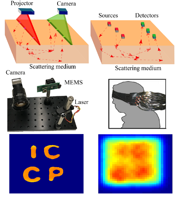
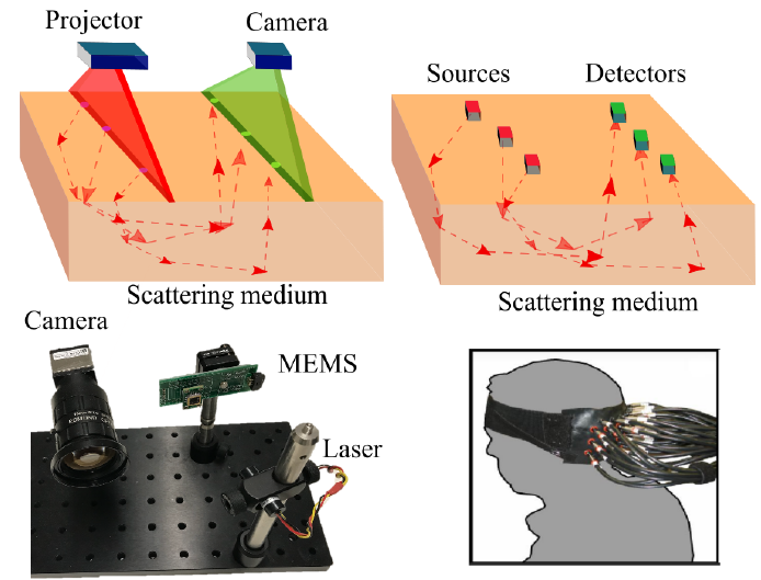
| Diffuse optical tomography (DOT) is an approach to recover subsurface structures beneath the skin by measuring light propagation beneath the surface. The method is based on optimizing the difference between the images collected and a forward model that accurately represents diffuse photon propagation within a heterogeneous scattering medium. However, to date, most works have used a few source-detector pairs and recover the medium at only a very low resolution. And increasing the resolution requires prohibitive computations/storage. In this work, we present a fast imaging and algorithm for high resolution diffuse optical tomography with a line imaging and illumination system. Key to our approach is a convolution approximation of the forward heterogeneous scattering model that can be inverted to produce deeper than ever before structured beneath the surface.We show that our proposed method can detect reasonably accurate boundaries and relative depth of heterogeneous structures up to a depth of 8mm below highly scattering medium such as milk. This work can extend the potential of DOT to recover more intricate structures (vessels,tissue, tumors, etc.) beneath the skin for diagnosing many dermatological and cardio-vascular conditions. | |||||||||||
Publications" High Resolution Diffuse Optical Tomography using Short Range Indirect Subsurface Imaging " |
|||||||||||
Illustration
| |||||||||||
Video | |||||||||||
|
| |||||||||||
|
We show the working scheme illustration and the reconstruction results in the video
|
|||||||||||
FAQsWhere does the convolution in the forward model come from? It comes from: (1) the usage of scanning illumination and camera exporue lines to replace the source-detector pairs in traditional DOT; (2) the isotropic light propagation direction distribution within dense scattering medium. For (2), the assumption holds true for dense scattering medium such as human skin. We test the robustness of our method against the failure of this assumption in the paper. Our method works for a wide range of scattering coefficients of the medium. Please refer to Section 6.1 for more details. What do the phase function and kernel depend on ? They depend on the source-detector (for traditional DOT using point sources and detectors) or the separation between the illumination and exporue lines (for our method), and the scattering and absorption coefficients of the homogeneous medium surrounding the heterogeneities. Given the line separation, how to get the phase kernel? In other words, how to get the absorption and scattering coefficients for the homogeneous medium ? We optimize the absorption and scattering coefficients of the homogeneous medium by solving an inverse problem for the homogeneous region. Theoretically the image intensities in a 1 x 1 area (a point) within the homogeneous region is enough to solve for the coefficients. We take a homogeneous region and calculate the mean values over the region to get the set of intensities to reduce noise. The homogeneous region can be either seleted manually, or automatically as the regions with low spatial contrast in all short-range indirect images. In the experiment, what is the maximal separation between the line illumination and camera exposure line on the surface ? In our experiment, the separation is up to around 10mm on the surface. The maximal separation setting depends on the sensed depth and data capture time budget. For larger separation, deeper heterogeneity can be sensed and reconstructed. But the signal is weaker due to more scattering and absorption, so we need to use longer camera exposures hence more time budget. The diameter of the laser spans several pixels in the image taken with a small FoV camera. Is this considered ? Yes. We pre-calibrate the 1D profile across the laser line illumination, and take that into account in the forward model as a spatial convolution. What is the black spot in the center of the short-range indirect images ? The black region is the artifact caused by the protection glass in front of the MEMS mirror we are using. Part of the laser light is reflected directly by the protection glass without being manipulated by the MEMS mirror. In addition, there is inter-reflection between the glass and MEMS mirror. As a result, in the raw image, there is a bright spot in the middle of image. This causes an issue especially for highly scattering medium since the region of the bright spot will be much larger than the laser spot itself due to subsurface scatterings. To ameliorate this issue, we subtract the "dark" image from the captured images, where the "dark" image is captured with the laser pointing outside the sample and FoV for the camera. However, because the inter-reflection between the glass and the MEMS mirror also depends on the MEMS mirror orientation, there is still artifact (the black region) in the center of the image after we apply the simple trick. A more straightforward and promising way to get rid of this artifact is to remove the protective glass. But that should be done in a clean room to avoid the contamination of the MEMS mirror. Is the method robust to the failure of the assumption in traditional DOT that the scattering coefficients of the heterogeneities and the surrounding homogeneous are close? Yes. We test the algorithm with different scattering coefficients for the heterogeneities and fixed scattering coefficient for the surrounding, using Monte Carlo simulated data. The performance does not degrade if the scattering coefficient of the heterogeneity varies. Please refer to Section 6.1 in the paper for more details. The specifications of the MEMS ? We use the Mirrorcle MEMS development kit. The scanning actuator is with the gimbal-less two-axis design. MEMS mirror is 1.2 mm in diameter, with operational angular range from -5 to 5 degrees in both x and y axis. We use the point-to-point (quasi-static) mode in order to project vector graphs. | |||||||||||
Related projectsHomogeneous Codes for Energy-Efficient Illumination and Imaging Matt O'Toole, Supreeth Achar, Srinivasa G. Narasimhan and Kiriakos N. Kutulakos ACM Transactions on Graphics (SIGGRAPH) 2015 Acquiring and Characterizing Plane-to-Ray Indirect Light Transport Hiroyuki Kubo, Suren Jayasuriya, Takafumi Iwaguchi, Takuya Funatomi, Yasuhiro Mukaigawa and Srinivasa G. Narasimhan IEEE International Conference on Computational Photography (ICCP) 2018 | |||||||||||
AcknowledgmentThis research was funded in part by NSF Expeditions ''See Below the Skin'' Grants #1730147 and #1730574, US Army Medical Research and Materiel Command "Autonomous Trauma Care in the Field" #W81XWH-19-C-0083 and a gift from the Sybiel Berkman Foundation. We thank Ioannis Gkioulekas for the insightful discussions and reviewers for their helpful feedback and comments. |