Exploring Tekkotsu Programming on Mobile Robots:

The Storyboard Tool

Prev: Shorthand notation
Up: Contents
Next: State signaling

Contents: Overview, Examining a storyboard, Modifying a layout, Generating an execution trace, Downloading a state machine model, Logging messages and images, Installing the storyboard tool

Overview

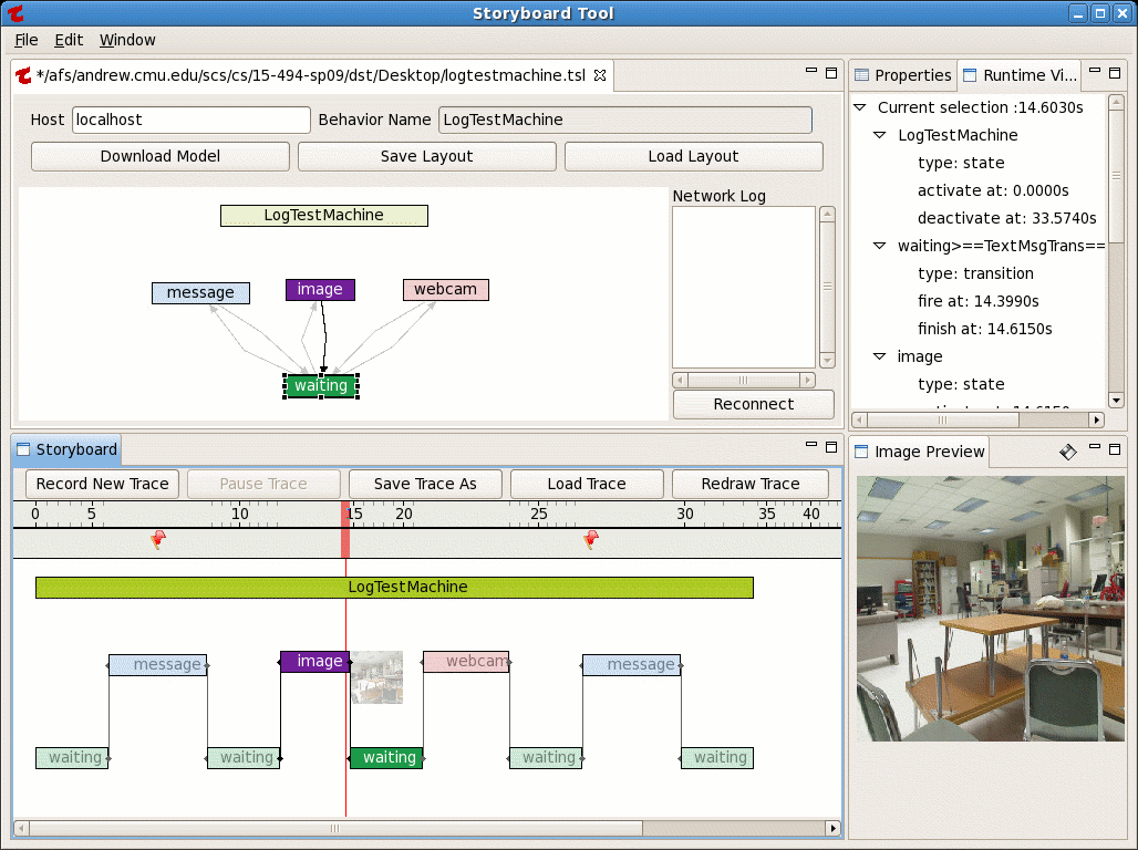
The Storyboard Tool allows you to monitor the execution of a state machine and display a graphical execution trace called a "storyboard". The tool is described in a 2004 senior honors thesis by Akkarit Sangpetch of Carnegie Mellon. In 2008-2009 it was substantially overhauled by Owen Durni. Click on the thumbnails below to see some representative screen captures.


The tool produces two types of files, both of which are encoded using XML representation:

  1. A layout file (extension .tsl) defines a state machine by listing the name and type of each state node, the name, type, sources, and destinations of each transition and how everything should be laid out on the screen. You can have multiple layout files to display the same state machine in different ways.

  2. An execution trace (extension .tse) is a record of a run of the state machine. It contains state activation and deactivation events, transition firings, sensor events, and other optional information, including user-generated messages. The layout file controls how the execution trace is displayed.


Examining a Storyboard

To begin using the tool, study the layout of the Storyboard display by clicking on one of the thumbnails above. The display is divided into two major section. The top half is the Layout pane; the bottom half is the Execution Trace (or Storyboard) pane.

Several sample layouts and execution traces are included with the Storyboard tool. In this section you will load a sample layout, and then use it to display a sample execution trace.

Loading Example Files

  1. Download these files to your hard drive: LogTestMachine.tsl, LogTestMachine.tse.

  2. Start the Storyboard Tool by running Tekkotsu/tools/Storyboard.

  3. Click on the "Load Layout" button, or select File > Open Layout from the pulldown menu. Select the file LogTestMachine.tsl.

  4. Click on a node and examine the information displayed in the Properties pane in the upper right. Click on a transition and do the same.

  5. Most of the bottom half of the window is taken up by the Storyboard pane. Click on the Load Trace button and load the file LogTestMachine.tse.

  6. Transitions are shown as black vertical lines. Try placing the mouse over the various transitions, nodes, and icons that appear in the Storyboard pane. You will see tooltips pop up to describe each item. Clicking on a node or transition will provide a more detailed description in the Runtime View tab in the upper right corner of the window. Notice that when you click on a state node in the Storyboard pane, the corresponding node in the Layout pane is highlighted. When you click on a vertical line denoting a state transition, the source and destination nodes and the transition arrow are all highlighted.

  7. Just below the timeline in the Storyboard pane is the event bar. You will notice two little flag icons indicating user message events. Hover over one of these flags with your mouse, and a tooltip will pop up showing you the message.

  8. The vertical red line in the Storyboard pane is the time index. You can click and drag on this index to move through the execution trace. As you do so, the highlighting changes, as does the information in the Runtime View tab.


Modifying a Layout

You can change the contents of a layout by deleting nodes and links, or adding them back in. The state machine model itself is not altered; the layout only controls which components are visible. You can change the appeearance of a layout by altering the position, size, shape, and color of nodes, and changing the shapes of transition arrows.

Changing the LogTestMachine Layout

  1. Click and drag the "message" node so that it is lower than the Image node. Notice that the execution trace is redrawn to reflect this change.

  2. Click on the "waiting" node in the Layout tab, and observe its properties in the Properties tab. Change the shape of the Waiting node from Rectangle to Ellipse by first clicking on the word "Rectangle" to bring up a menu of shapes. Then click on "Ellipse" and hit Return.

  3. Change the color of the "waiting" node to brown by clicking on the "Color RGB [...]" text, then clicking on the square icon that appears on the far right, and selecting the new color.

  4. Right click on the "webcam" node, and select Delete from the pop-up menu. The node and all its transitions should disappear from the layout.

  5. Right click on an empty spot in the Layout pane, and from the pop-up menu, select Add State. Then select "webcam". Move the node to its previous position, but a little lower, so it is aligned with the "message" node, and below the "image" node. Adjust its width.

  6. Right click on an empty spot again, and from the pop-up menu, select Add Transition. Then select one of the transitions and add it back in.


Downloading a State Machine Model

Layout files describe how a state machine should be displayed. The layout contains a model of the state machine which is is created by downloading the information from the roobot. When the Storyboard tool connects to the robot, it can examine any running state machine. In this section we will download a model and use it to create a layout.

Downloading the Bark/Howl/Blink State Machine Model

  1. Start up Tekkotsu and connect to the robot with the ControllerGUI.

  2. If you don't already have a Storyboard running, type "Storyboard" to launch it, or run Tekkotsu/tools/Storyboard if it's not on your search path.

  3. Type your robot's host name in the Host box. If you're running in the simulator, use "localhost" as the host name. Type BarkHowlBlinkBehavior in the Behavior Name box.

  4. Your behavior must be running in order for the Storyboard to be able to see it. Use the ControlelrGUI to activate it.

  5. Click on Download Model in the Storyboard tool. You should see the XML for the model scroll by in the network log, and a dialog box will pop up asking if you would like to generate a layout for the model. Click "yes", and the model should appear. (If you instead click "No", you can manually add nodes and transitions by right-clicking in the Layout pane.) Deactivate the behavior once you have the model.

  6. Switch to the Layout pane. Edit the layout until it looks roughly like the state machine diagram in the tutorial. Change the color of the transition from Bark to Wait to bright red.

  7. Click on the Save Layout icon, or select "Save Layout" from the File pulldown menu. Call your file bark.tsl.

  8. Go to Root Control > Status Reports > Event Logger and turn on logging for buttonEGID. Make sure the robot is un-stopped so it can receive button press events.

  9. Click on "Record New Trace" in the Storyboard pane, and activate BarkHowlBlinkBehavior again. You are now generating a storyboard using the model and layout you created. If in response to a short bark, you push the green button, you will cause the red transition to fire, which will result in a red vertical line in the storyboard instead of the usual black line.

  10. When you've completed the trace, stop the behavior in ControllerGUI, and hit the Pause Trace button in the Storyboard pane. Then click on the "Save Trace As" button in the Storyboard pane and save your trace to the hard drive.


Logging Messages and Images

You can log messages to the storyboard under program control, like the Message node did in the LogTestMachine example. You can also send robot camera images to the storyboard, or tell the Storyboard Tool to snap a picture with a webcam (presumably pointed in the general direction of the robot) and log that to the storyboard. The following is a simplified version of LogTestMachine that illustrates these features.

#include "Behaviors/StateMachine.h"
#include "Behaviors/Controls/EventLogger.h"
#include "Shared/ProjectInterface.h"
#include "Vision/JPEGGenerator.h"

$nodeclass LogTestMachine : StateNode {

  $nodeclass Message : StateNode : doStart {
    std::string const msg = "Hooray for Captain Spaulding!";
      EventLogger::logMessage(msg,this);
  }

  $nodeclass Image : StateNode : doStart {
      EventLogger::logImage(*ProjectInterface::defColorJPEGGenerator,ProjectInterface::fullLayer,0,this);
      sndman->playFile("camera.wav");
  }

  $nodeclass Webcam : StateNode : doStart {
    EventLogger::logWebcam(this);
  }

  $setupmachine{
    startnode: StateNode
    startnode =TM("message")=> Message =N=> startnode
    startnode =TM("image")=> Image =N=> startnode
    startnode =TM("webcam")=> Webcam =N=> startnode
} } REGISTER_BEHAVIOR(LogTestMachine);

This behavior uses a TextMsgTrans to look for messages from the ControllerGUI and transition to the appropriate state node. If you run this behavior and type "!msg message" in the ControllerGUI's Send Input box, it will log a message to the storyboard, while "!msg image" will log a camera image.

Installing the Storyboard Tool

There are separate versions of the Storyboard Tool for 32 bitLinux and Mac OS X. Since they're relatively large files, and are operating system-specific, they are not included as part of the standard Tekkotsu distribution. So if you do not have a Tekkotsu/tools/storyboard/ directory, you will have to download the version you need. See the Tekkotsu wiki page on Storyboard install instructions.

Prev: Defining new types
Up: Contents
Next: State signaling


Last modified: Wed Jun 5 15:25:42 EDT 2013