With all PB3A system programs executing, your system should look something like this.
Now, in the Module Manager's file menu, select "File" then "New"
to construct a new PB3A system. If all is running properly, your
system should look something like this. (Of course, I painstakingly
arranged the windows to look pretty.)
![]()
With all PB3A system programs executing, your system should
look something like this.
We now want to see what agents are available to the system. To
locate the agents, click the "Network" folder (to have the Module
Manager query the Agent Server), then click the "adaptive" folder, and
finally the "agents" folder. At this point, there should be five
agents, and the Module Browser should look like this.
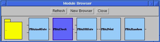
These should be the available agents with which you can
construct a PB3A system.
PBAClock agent has no inputs and a single boolean output that
switches from low to high every 300 milliseconds. PBAAndGate takes
two boolean inputs and outputs the logical AND of them every 1000ms.
PBAORGate takes two boolean inputs and outputs the logical OR of them
every 1000ms. PBARandom outputs a random double-precision,
floating-point number every 1000ms. PBAPrint simply prints the value
of its input (whatever type that may be) to the Net Controller.
We're now ready to begin laying out the agents. First, select the
PBAClock by left-clicking on the image in the Module Browser. Next,
click to a point on the Module Manager's canvas to drop in a new
PBAClock. Add two PBAClock agents to the canvas. The canvas should
look like this.
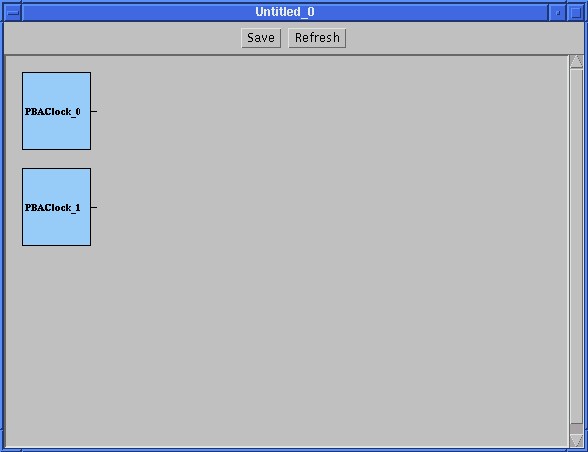
Picture of the canvas after adding PBAClocks to it.
In a similar process, add one PBARandom. Next, add two
PBAAndGates to the system. Finally, add two PBAORGates to the system.
The system should resemble this.
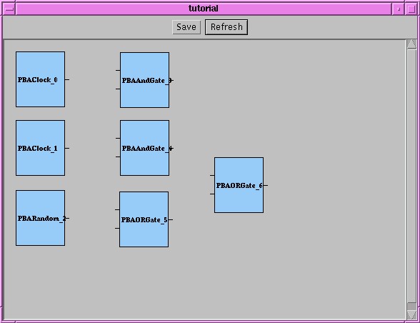
After adding the Clocks, a Random, two AND gates, and two OR
gates.
All right!! We're now ready to begin mapping the input ports!
From the Module Manager menu bar, select the button "Map".
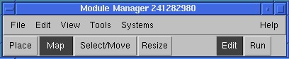
Selecting the "Map" mode allows us to connect input/output
ports in the system.
Input ports to an agent are always on the left side of it, and
output ports are always on the right. First, connect the output of
PBAClock_0 (the top-left-most agent in my layout) to the top input port
of PBAAndGate_3. This is done by clicking the output port of
PBAClock_0 and then clicking the top-most input port of PBAAndGate_3.
In the same fashion, connect also connect the output port of
PBAClock_0 (the same clock agent) to the top-most input port of
PBAORGate_5. Output ports can serve as input to any number of
input ports (including none), but every input port must be connected
to one, and only one, output port. After connecting the output,
your system should look something like this.
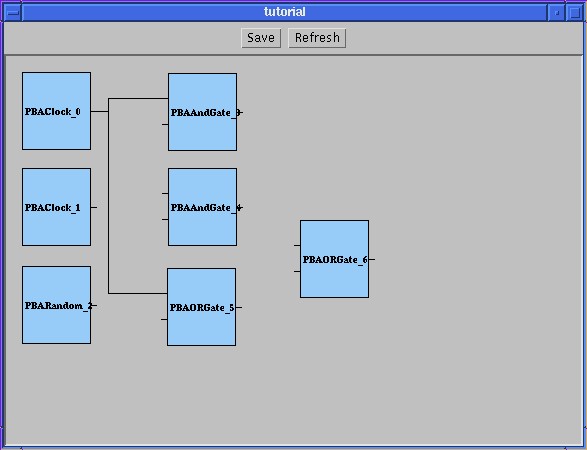
My system after connecting PBAClock0's output
ports.
Now, map the output of PBAClock_1 to the bottom input port of
PBAAndGate_3 and both ports on PBAAndGate_4. Your system should now
look like this.
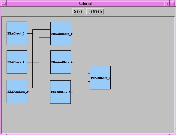
After connecting both PBAClock0's and PBAClock1's output ports,
my system looked like this.
Now, we're going to try and map the output of PBARandom_2 to the
input of PBAORGate_5. When you do this, the happy smiley face should
turn into a big stop sign. And displays an error.
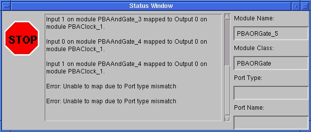
Connecting PBARandom's output port to PBAORGate's input is
invalid.
"But why", you ask, "is this an error?" Well, the output of
PBARandom is the Java type "Double" and the input of PBAORGate is the
Java type "Boolean". It is only legal, and only makes sense, to
pass information from an output port to an input port when the output
port's data type (i.e., Java class) is the same type as, or a
sub-class of, the data type of the input port. So, let's not try
to make this connection then... Click the stop sign to bring back
that comforting smiley face. Hit the ESC key to cancel the attempt to map
that port.
OK, let's map the output of PBAAndGate_4 to PBAORGate_6 and map
the output of PBAORGate_5 to PBAORGate_6. Your system should look
like this.
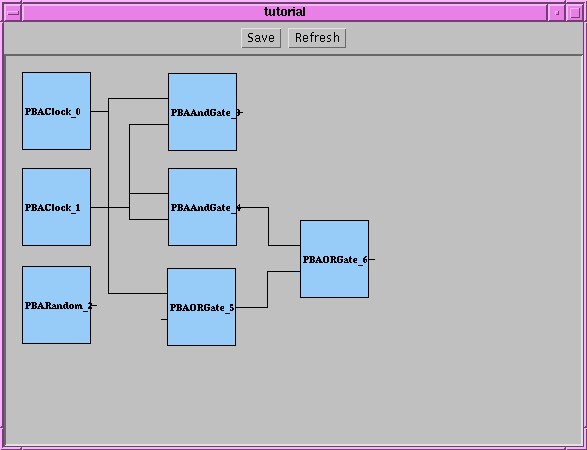
OK, my system is about ready to be launched.
Starting a PB3A Program
Back to the Beginner's Guide.