Introduction to Mechanisms
Yi Zhang
with
Susan Finger
Stephannie Behrens
Mechanisms can be divided into planar mechanisms and
spatial mechanisms, according to the relative motion of
the rigid bodies. In a planar mechanisms, all of the
relative motions of the rigid bodies are in one plane or in parallel
planes. If there is any relative motion that is not in the same plane
or in parallel planes, the mechanism is called the spatial
mechanism. In other words, planar mechanisms are
essentially two dimensional while spatial mechanisms are three
dimensional. This tutorial only covers planar mechanisms.
Kinematics of mechanisms is concerned with the motion of
the parts without considering how the influencing factors (force
and mass) affect the motion. Therefore, kinematics deals with the
fundamental concepts of space and time and the quantities velocity and
acceleration derived there from.
Kinetics deals with action of forces on bodies. This is
where the the effects of gravity come into play.
Dynamics is the combination of kinematics and
kinetics.
Dynamics of mechanisms concerns the forces that act on
the parts -- both balanced and unbalanced forces, taking into account
the masses and accelerations of the parts as well as the external
forces.
A link is defined as a rigid body having two or more
pairing elements which connect it to other bodies for the purpose of
transmitting force or motion (Ham
et al. 58).
In every machine, at least one link either occupies a fixed position
relative to the earth or carries the machine as a whole along with it
during motion. This link is the frame of the machine and
is called the fixed link.
The combination of links and pairs without a fixed link is not a
mechanism but a kinematic chain.

Figure 3-1 Skeleton outline
For the purpose of kinematic analysis, a mechanism may be represented
in an abbreviated, or skeleton, form called the skeleton
outline of the mechanism. The skeleton outline gives all the
geometrical information necessary for determining the relative motions
of the links. In Figure 3-1, the skeleton outline has been drawn for
the engine shown in Figure 2-1. This skeleton
contains all necessary information to determine the relative motions
of the main links, namely, the length AB of the crank; the length BC
of the connecting rod; A the location of the axis of the main bearing;
and the path AC of point C, which represents the wrist-pin axis.
A pair is a joint between the surfaces of two rigid
bodies that keeps them in contact and relatively movable. For
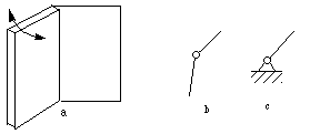
example, in Figure 3-2, a door jointed to the
frame with hinges makes revolute joint (pin
joint), allowing the door to be turned around its axis. Figure
3-2b and c show skeletons of a revolute joint. Figure 3-2b is used
when both links joined by the pair can turn. Figure 3-2c is used when
one of the link jointed by the pair is the frame.

Figure 3-2 Revolute pair
In Figure 3-3a a sash window can be translated
relative to the sash. This kind of relative motion is called a
prismatic pair. Its skeleton outlines are shown in
b, c and d. c and d are used when
one of the links is the frame.

Figure 3-3 Prismatic pair
Generally, there are two kinds of pairs in mechanisms,
lower pairs and higher pairs. What
differentiates them is the type of contact between the two bodies of
the pair. Surface-contact pairs are called lower pairs.
In planar (2D) mechanisms, there are two
subcategories of lower pairs -- revolute pairs and prismatic
pairs, as shown in Figures 3-2 and 3-3, respectively.
Point-, line-, or curve-contact pairs are called higher
pairs. Figure 3-4 shows some examples of higher pairs
Mechanisms composed of rigid bodies and lower pairs are called
linkages.

In kinematic analysis, a particular given mechanism is
investigated based on the mechanism geometry plus other known
characteristics (such as input angular velocity, angular acceleration,
etc.). Kinematic synthesis, on the other hand, is
the process of designing a mechanism to accomplish a desired
task. Here, both choosing the types as well as the dimensions of the
new mechanism can be part of kinematic synthesis. (Sandor & Erdman 84)

Complete Table of Contents
- 1 Introduction to Mechanisms
- 2 Mechanisms and Simple Machines
- 3 More on Machines and Mechanisms
- 3.1 Planar and Spatial Mechanisms
- 3.2 Kinematics and Dynamics of Mechanisms
- 3.3 Links, Frames and Kinematic Chains
- 3.4 Skeleton Outline
- 3.5 Pairs, Higher Pairs, Lower Pairs and Linkages
- 3.6 Kinematic Analysis and Synthesis
- 4 Basic Kinematics of Constrained Rigid Bodies
- 5 Planar Linkages
- 6 Cams
- 7 Gears
- 8 Other Mechanisms
- Index
- References


sfinger@ri.cmu.edu
| 
