- A. Object Detection from Stationary and Moving Sensors
Visual detection of moving targets using a stationary camera is performed
using a simple yet effective backgrounding algorithm. An adaptive background
model is constructed and constantly updated using an AR filter. Frames are
"differenced" with the background model to separate the foreground (moving
objects). The strength of this scheme is dramatically increased by feedback from
the higher level processing by the classifier agent and the
tracking/correspondence agent. This agent collaboration leads to an important
behavior: Increased performance when simple, dependent algorithms interact with
each other effectively.
Moving Sensors (K. Bhat)
The algorithm described above is being extended to the scenario where the camera
is panning. A panaromic background model of the scene is constructed by mosaicing
a spatial sequence of images. The mosaic is constructed by stitching together
images referenced by features deemed common to them. The background and image in
the panaroma are matched by modeling the relationship of the change in the
camera's position with the change in pixels. For more info, click here.
B. Object Classification Over Time and Across Sensors
(C. Diehl)
As the motion detector nominates targets viewed by the sensors in the
environment, the classifier agent, working in collaboration with the
tracking/correspondence agent, must determine the target types present.
In order to perform such an assessment in a robust, efficient manner, we
will leverage the capability of a distributed surveillance system to
observe targets from multiple perspectives over time. Instead of
devoting computational resources to reducing the effects of various
distortions on the decision process, we advocate using a simple
classification procedure with a rejection option and integrating
classification decisions made after each look at the target. Through
such a process, we believe we will be able to mitigate the effects of
malicious or ambiguous data while minimizing the computational demands
on the sensing systems.
C. Object Correspondence, Tracking and Geolocation
(M. Saptharishi)
The problem of target correspondence is defined as corresponding a target seen by
sensor s1 at time t with the target seen by sensor s1 at time t+1. The problem of
target tracking is defined as correspondence accompanied by decisions to pan,
tilt or move the sensor so as to keep target in the field of view of sensor
network S = {s1, s2, ...., sN} as long as possible. The problem of target handoff
is defined as matching target (Ti,sj) (ith target seen by jth sensor) with (Tk,
sl), j != l. Correspondence is performed using a combination of linear prediction
of the target's position and feature based matching. It is assumed that the
sensor network S is in an uncalibrated environment. Thus, target handoff is
performed using feature matching and online learning of the sensor network S's
spatial topology. Tracking is performed so as to maximize probability of target
handoff based on the learnt spatial topology of the sensor network.
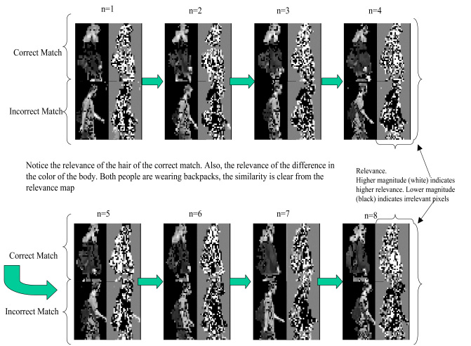
We have developed a novel feature selection and correspondence scheme using
a technique called Differential Discriminative Diagnosis .
Differential Discriminative Diagnosis finds stable features on
moving objects that are most relevant to a discrimination task.The basic
discrimination task is performed using a single output logistic linear neural network.
Differential Discriminative Diagnosis is used to customize the classifier
to a particular moving object. The customization step diagnoses the neural network to
find the features that are the most relevant to the discrimination task.
Figure 1 shows an example of the correspondence
using Differential Discriminative Diagnosis.
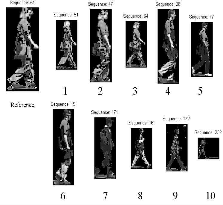
This same correspondence technique can also be used to retreive similar moving
objects from a database. In addition to retreiving similar objects, the algorithm
also retreives instances of the same object occuring at different times.
Figure 2 shows that the algorithm picked two
other sequences of the same person in addition to picking the top ten matches from
a possible 249 sequences containing a total of more than 3000 images.
(matches 2 and 3).
- A. Obstacle Detection and Avoidance Using Multiple Cues
We are currently using vision as our main sensor modality for obstacle
detection. Its passive and unobtrusive nature, notable progress in the
area, plus the evidence of powerful biological systems indicate that this
is a viable alternative. Our approach to visual perception is an adaptive
integration of multiple visual cues.
In general a dynamic unconstrained environment allows for many
interpretations. Patterns, tendencies and models lay in a complex high
dimensional space of shapes, colors, sounds, past experiences, knowledge,
and so on. In contrast to other sensor modalities, vision can allow the
perception of a large number of different features of the environment
suchas color, shape, depth, motion, and so on. Depending on the task and the
environment, the quantity of information or entropy in each visual cue
canfluctuate. An efficient adaptive integration of visual cues should
consider the task and environment constraints to reduce ambiguity.
Using these ideas, we have implemented obstacle detection algorithms
based on color and stereo disparities, and currently we are working on adding
algorithms to detect motion and image textures.
B. Range Information Derived from Stereo Vision
(A. Soto)
The principle used by stereo vision to provide range information is based
on the comparison of the projection of world points on two or more
images. The key points to obtain an accurate stereo map are the knowledge of the
relative position of the cameras (calibration problem) and the position
of the projections of world points to different images (correspondence
problem).
In our system the calibration problem is solved using a 3-D cube of known
dimensions and position with respect to the stereo pair. Using this cube
and standard calibration techniques we can obtain the intrinsic and
extrinsic camera parameters. In order to facilitate the stereo
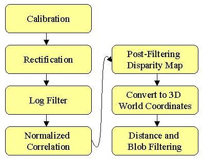
correlation, two pre-processing steps are applied to the input images. First, the
images are rectified in order to align the epipolar lines with the horizontal
scan lines of the video cameras. Second, the images are convolved with a
Laplacian of a Gaussian (LoG) filter. This filter not only allows
eliminating high frequency noise and intensity asymmetries between the
images, but it also enhances the image textures. In the case of the
correspondence problem, we are using a normalized correlation method.
Figure 3 shows the main step
of the stereo processing. The post filtering
of the disparity map allows to eliminate outliers due to lack of texture,
differences in foreshortening, occlusions, or repeated patterns in the
images. The blob filtering using XYZ real world coordinates allows to
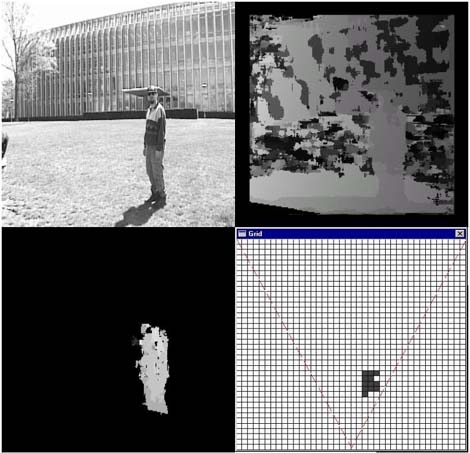
detect only the obstacles that are important for the navigation. Figure 4
shows an input image, the initial disparity map, the detection of an
obstacle, and the projection of this obstacle to a occupancy grid.
C. ColorTexture
(A. Soto)
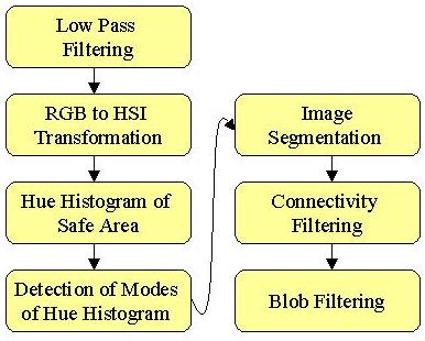
We have been using color segmentation for the detection of areas free of
obstacles in structured environments. The basic idea is that
ground-planes of structured environments, such as grass field or roads, usually present
a homogeneous intensity or color, which can be easily identified through
color segmentation techniques.
The technique uses a Hue, Saturation and Intensity (HSI) color model to
perform image segmentation based on histogram analysis. The main
advantage of HSI is that it allows a nice decoupling of the color and intensity
information. Also the use of histograms allow a very fast processing.
Using the stereo vision system, we detect in the images floor areas free
of obstacles. These areas are used to build hue histograms. If the floor
patches have a homogenous or texture pattern with with a caracteristic
hue information, the resulting histogram is multimodal. A simple analysis of
the peaks and valley of this histogram allows setting adequate thresholds
to distinguish between obstacles and floor points. The rest of the
algorithm uses these thresholds to segment the image points between
obstacle and floor candidates, and then a connectivity and blob filtering
analysis produces the final obstacle detection. Figure 5 shows the main
step of the algorithm.
Figure 6 shows the result of the obstacle detection using the HSI-based
segmentation on a grass field. There are two important observations about
the images. First, note the correct detection of the shadow of the person
as not an obstacle. Although this shadow produces a large variation in
intensity, the decoupling of intensity and color allows keeping in the
hue component only the color information. Also note how the green pants of
the person are incorrectly detected as not obstacle. This is a limitation of
the algorithm, but fortunately in our grass field the probability of
finding a green person or a completed green obstacle is extremely low.
Even if this happens, still the obstacle can be detected by the stereo vision
system.
D. Cue Integration: An Adaptive Perceptual Control Scheme
(A. Soto)
The obstacle detection based on stereo vision relies on very general
principles but it allows only a very slow sample rate. On the other hand the
color segmentation works properly only when the floor has some specific
properties but it allows a very fast sample rate. The idea is to
integrate these and other visual cues under a adaptive perceptual control scheme in
order to achieve an efficient and robust visual perception. At the moment
we are exploring some learning techniques to develop an initial version
of this adaptive perceptual control scheme.
E. Sidewalk Following
(K. Bhat, M. Savvides)
This work enhances the capabilty of the ATVs to traverse autonomously in an urban scenario by detecting and following sidewalks. The ATV grabs an image of the ground in front of it, segments the sidewalk from other portions of the image and navigates on the sidewalk. When it detects a sidewalk intersection, it stops and sends an image of the scene in front of it to the user. The user, located at a remote location, can view the image and can guide the ATV to any desired path. This capability is very useful in places where the GPS communication is poor (or non existant). Several techniques were implemented for sidewalk segmentation, ranging from simple intensity based band-pass filters to more sophisticated log-likelihood classifiers. The latter method used 4 classes, 1 for sidewalk and 3 for non-sidewalk regions, and the input vector is the 3 color components of a image block. The means and variances of the sidewalk class are adjusted to the current illumination conditions. The current algorithm works pretty well under various illumination conditions, and on sidewalks with shadows.
- A. CyberARIES - Autonomous Reconnaissance and Intelligent Exploration System
CyberARIES is a distributed software agent infrastructure running on every node of the CyberATV sensor network. CyberARIES works on a very small computational and memory budget. ARIES provides resource management in the form of automatic thread scheduling, network abstraction and memory management for the agents. The agents inherently process and learn from large amounts of data and thus necessitate such a system. ARIES interfaces with the distributed C3 and simulation interface: CyberRAVE. RAVE provides user interfaces and high level operations such as task decomposition.
---Coming Soon---
A methodology is currently being developed for specifying and coordinating the mission plan of a distributed, mobile, surveillance system. The mission planner will first be demonstrated on a building stake-out scenario with incomplete a priori information about the dynamically changing workspace. The mission planner will allow for autonomous or user-in-the-loop operation. First an area is selected for surveillance, and then the best possible placement of sensors for monitoring the area is determined. The surveillance task is decomposed, and the subtasks are assigned to various ATVs. Each ATV is then responsible for planning its own path to the goal location. An autonomous software agent will analyze the combination of plans and may reorder individual plans in such a way as to minimize conflict and maximize probability of global mission success. From this global plan, which does not reside on any one ATV, the Checkpoint Priority Action Database (CPAD) is constructed. The CPAD is responsible for coordinating the motions of ATVs at possible intersections by assigning or updating relative priorities as new information is obtained. This database also allows for other coordinations to be incorporated into the mission plan (e.g. autonomous convoying, recognizing and planning around moving obstacles). Thus it is shown that CPAD can be a useful tool for dynamically structuring mission specifications.
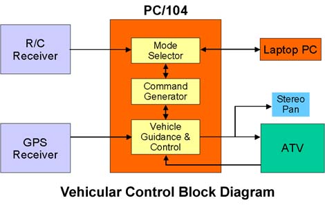
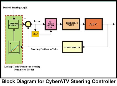
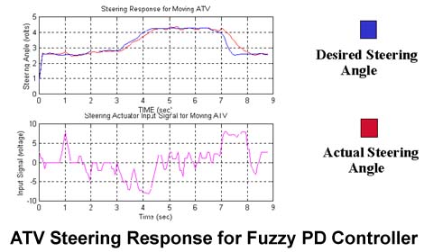
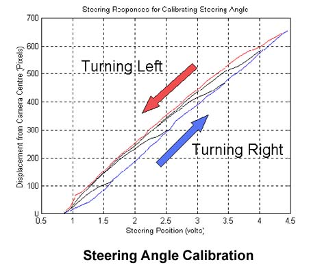
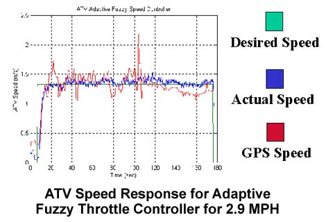
The autonomous control architecture design is partitioned into three levels (see Figure 7). The highest level of control, the Task module, executes mission tasks phrased in symbolic terms, e.g., “explore the environment”. The highest level of control is built into CyberRAVE and therefore will not be presented here. See [5] for further details. The lowest level of control, the vehicular control module, and it drives the actuators for steering, braking, throttle, and monitors navigation sensor data (position, velocity, acceleration and posture) of the mobile platform. The mid-level of the control architecture is called CyberAries (Autonomous Reconnaissance and Intelligent Exploration System). CyberAries is designed according to an agent-based computational paradigm. The CyberAries and vehicular control blocks are resident on the high-level (Pentium II 350 MHz) and low-level (PC/104) vehicle processors, respectively. CyberRAVE is usually resident on a remote laptop or workstation, and it is linked to CyberAries via a wireless Ethernet using 915MHz Wavelan technology. Communication between the vehicular control block and CyberAries is via a RS232 serial cable. The rest of the section will detail some of the critical components of the vehicular control block and CyberAries. Vehicular Control Block The vehicular control block (Figure 8) receives commands from CyberAries, e.g. mode selection, desired position, desired steering angle, etc. The vehicular control block also feeds back the vehicle states, e.g., speed, steering angle, position and posture to CyberAries. There are two basic modes in the vehicular control block, manual and autonomous Mode. In manual mode, the four functions of the vehicle can be controlled directly from CyberRAVE (using a laptop or wearable computer) or a radio control joystick. Remote control of the vehicle is currently done using line of sight, but a teleoperational system is being considered. In autonomous mode, CyberAries commands desired speed and waypoints to the vehicular control block. Waypoint navigation is accomplished using GPS for position feedback and pure pursuit steering. The automatic control of gearing and braking involves the straightforward setting of various hydraulic valves. Speed/throttle and steering control, however, involve interesting challenges which are detailed below. Steering control for ATV The objective of the steering control system design is to provide precise locomotion, pointing, posture and robustness to external disturbances. A block diagram of the steering controller is shown in Figure 9. A simple initial design was bang-bang control. This resulted, however, in large errors and instability when small steering angles were commanded. A fuzzy PD controller was then developed using data collected and experience gained from the bang-bang control scheme. The fuzzy PD algorithm was found to produce smooth control and fairly accurate pointing for navigation and visual tracking. Figure 10 depicts the ATV steering response to commanded steering angle. The described steering control was initially applied to the voltage feedback received from the steering potentiometer. Due to mechanical hysteresis in the steering, however, this voltage is not linearly related to the actual steering angle. An experiment was set up to calibrate the output of the steering potentiometer to the effective front wheel angle. Based on measurements characterizing the steering hysteresis loop, we developed a steering model, which establishes the nonlinear relationship between voltage and angle (Figure 11 , in which pixels correspond to steering angle). This model allows us to reduce steering angle error from as great as 5 degrees to +/-1 degree. Speed Control Since the ATV is equipped with cameras for navigation, it is essential that the vehicle move smoothly at fairly low speeds that will allow real-time processing of images. A block diagram of the speed controller is shown in Figure 12. The two main challenges in designing an effective speed controller for the ATV are: · the lack of a complete mathematical model for the engine; · the highly nonlinear nature of the engine dynamics, especially for the target low speed range of 3-30MPH; · the belt slippage of the Automatic Polaris Variable Transmission (PVT) at low speeds. Each of these factors makes the use of classical control strategies such as PID control ineffective. Using experience and data collected from extensive experiments conducted on the ATV throttle mechanism, an adaptive fuzzy throttle control algorithm was designed [2]. A candidate Lyapunov function was employed in the adaptive law synthesis to ensure convergence. The adaptive fuzzy throttle control produces smooth vehicle movement, robustness with respect to varying terrain, and commanded speeds in the range 2MPH to 30MPH. Figure 13depicts the ATV speed response to a selected speed. The described low-level control algorithms have been implemented on two other ATVs with very little modifications in line with the design objectives.