| Reconfigurable Computing Seminar | 2/9/98 |
 Slide 1: Multi-Context FPGAs
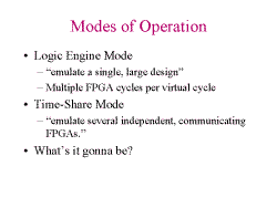 Slide 2: Modes of Operation
The first thing to think about when in Logic Engine Mode is that it looks bigger than it is.
Discussion: How does PipeRench work? Stripe is like FPGA communicating with ones above and below it. With this design (not PipeRench), we are still limited by space. We only have 8 configurations that can be used at a time. In a way, the number of confuration cycles per user cycle determine the mode.
Something to think about, what are they trying to emulate?
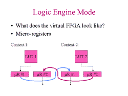 Slide 3: Logic Engine Mode
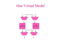 Slide 4: One Virtual Model
This slide shows Slide 3 flattenned. They can communicate any way you want through the registers.
What's wrong with this slide? There's a micro-register between LUT 0 and LUT 1. But if we do temporal pipelining (context 0, then 1, then 2 ... then 0), the register locally disappears. So there is a crossbar between all contexts. Except that when a microregister connects a context with one BEFORE it (8 -> 5). In that case, the microregister becomes a logical register, because the logical clock occurs between the evaluation of context 8 and context 5. It's a weird virtual architecture. Virtualization should make the model easier to understand and design to, not harder.
Are eight configurations enough? This design is good for 8 independent architectures that time-share the hardware. In the DHARMA paper the minimum number of contexts required for any of the benchmarkes is nineteen. What happens if you only have eight? Let's say the DHARMA cell is a NAND gate. You must do significant chaining of LUTs in order to get to fit into 8 contexts. Is a comparison fair? You can't do one level of logic per context.
How about efficiency in design? The Xilinx multi-context FPGA
is 8 contexts and is 3 times as large. Therefore you have to obtain
at least 60% cross-context utilization to break even. Their
agenda is to build a big FPGA has a lot of problems. What about
a tiled approach? Then you only need to worry about
boundaries. Tiled approach is PipeRenchish with huge stripes.
Problems: what to do about circular dependencies, and dependencies
that go backwards as well as forwards.
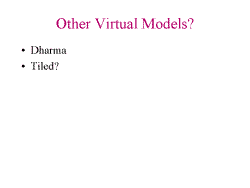 Slide 5: Other Virtual Models?
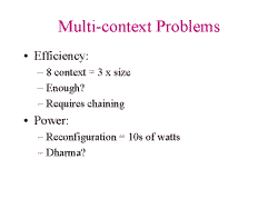 Slide 6: Multi-context Problems
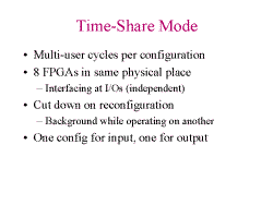 Slide 7: Time-Share Mode
Locality- does it happen in the FPGAs?
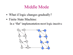 Slide 8: Middle Mode
 Slide 9: FSM Partitioning
Locality of State allows reduction in next state decoder and
output decoder. Both smaller and faster implementation.
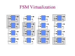 Slide 10: FSM Virtualization
 Slide 11: Data Dependency Reconfiguration
 Right hand design is smaller. Where does decoding happen? The middle, you have more control and smaller inctructions.
Reconfigurable implementations sort of look like the middle diagram.
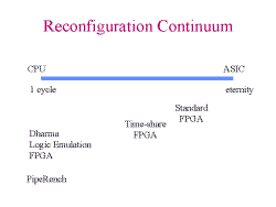 Slide 12: Reconfiguration Continuum
In the figure, the hardware becomes less general and more specific from
left to right. More performance increasing from left to right as
well. Capacity increases from right to left.