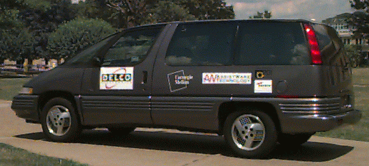
Figure 1. The Navlab 5, a 1990 Pontiac Trans Sport.
Figure 1. The Navlab 5, a 1990 Pontiac Trans Sport.
Our newest vehicle, the Navlab 5, is a 1990 Pontiac Trans Sport donated to us by Delco Electronics. See Figure 1. This vehicle is used for on-road navigation experiments including autonomous lane keeping, lateral roadway departure warning and support, and curve warning. These task-specific systems run on the PANS platform (Portable Advanced Navigation Support). The platform provides a computing base and I/O modalities for system developers as well as low level services like position estimation, steering wheel control, and safety monitoring. The PANS platform is powered from the vehicle's cigarette lighter and is completely portable.
All high level processing, including position estimation and vehicle control, is done on a Sparc LX class portable workstation equipped with a color video digitizer. The only additional processor is an HC11 microcontroller that implements functions like low level steering motor control and safety monitoring.
Position estimation is done on the PANS platform using input from 2 sensors - a differential equipped GPS and a fiber optic rate gyro. When available, a steering wheel position encoder is also used. Local (x, y, heading) and global (latitude and longitude) position along with vehicle velocity, distance traveled, and turn radius, are supplied to application programs using an interprocess communications mechanism.
Over the past 6 months, the PANS platform has supported over 6000 miles of autonomous lane keeping including 30 miles on a closed test track where the Navlab 5 reached a top speed of 90 m.p.h. PANS has also been used by other systems to provided passive and active lane departure warning and support on many road types including city streets. Our map based curve warning system has used the global positioning data supplied by the PANS position estimation module to locate upcoming curves and warn the driver to slow down if they are approaching too quickly.
The Navlab 2, a converted US Army HMMWV, is a good platform for off-road navigation, where extra ruggedness is necessary and short (less than 10 miles) missions are the norm. It is not well suited for on-road driving research because of its size, complexity, and temperamental operational nature. Also, on-road driving systems have progressed to the point were experimental runs in the hundreds or even thousands of miles have become practical.
PANS was designed to address these issues. It uses simple, well engineered commercially available components, that were integrated in a straightforward manner. And because it is designed to be used in a unaltered passenger vehicle, it has no special power or cooling requirements. Also, the future users of the system were involved from the beginning in the design, fabrication, and operationalization of all PANS components. This effort led to a highly usable and maintainable platform.

Figure 2. PANS components inside the Navlab 5.
All high level application computing is done on a Sparc LX class portable computer manufactured by RDI Computer Corporation. See Figure 2. Key components of this computer are a 50MHz MicroSparc CPU, 32 MB's of RAM, 970 MB's of hard disk space, and a 1024x768 active matrix LCD display. (For comparison, this processor is about equivalent to a 486DX2/66 using Spec ratings as a guide.) The laptop contains an optional Peripheral Expansion Unit which is equipped with two SBUS slots and space for additional hard disk drives. The two SBUS slots contain a Datacell color video digitizer and a Performance Computer Company quad serial port expansion unit. The laptop runs SunOS 4.1.x.
The digitizer input is connected to a Sony DXC-151A color camera. The camera is outfitted with a Pelco TV8 ES-1 auto iris, manual focus lens. This camera/lens combination has proven to be exceptional in providing high quality images even in harsh conditions like heavy shadows in bright sunlight and at night, using only the vehicle headlights for illumination. This camera provides RGB as well as NTSC video output. The camera can be mounted in two different position, depending on the software system that is in use. When using PANS to test forward looking lateral vehicle control and driver monitoring algorithms, it is mounted on the rear view mirror mounting bracket. See Figure 2. For the downward looking lateral lane position system it is mounted on a special suction cup plate, which is attached to the side window of the vehicle.
The output from the digitizer, which is usually just a playthough of the incoming video signal from the camera along with overlay graphics, is connected to a Sony FDL-X600 color LCD monitor. See Figure 2. The display is mounted on the dashboard, directly in front of the forward passenger seat.
A key component for both our local and global positioning algorithm is a Trimble SVeeSix - CM2, differential ready GPS system. This unit's specifications are typical for entry level 6 channel GPS receivers: 25 meter position and 0.1 meter/second velocity accuracy without SA. The positional accuracy figure improves to 2 - 5 meters when operating in differential mode. These numbers have been experimentally verified to be correct. The GPS unit is interfaced to the portable computer using a serial line.
Differential corrections are supplied by a Navstar base station unit, mounted at a known location on a tower on top of our vehicle storage area. This unit supplies standard RTCM-104 differential corrections using Motorola Cellect modems over a cellular phone link to the SVeeSix. This distribution mechanism has proven to be robust in areas of poor cellular coverage and over extremely long baselines.

Figure 3. Electronics box containing GPS, HC11, and power distribution
equipment. Fiber optic gyroscope is also shown.
The second component which is integral to the PANS positioning system is an Andrew Corporation AUTOGYRO� with digital output. See Figure 3. This fiber optic gyroscope provides updates to the position estimation system running on the portable computer at 10 Hz using a 9600 baud serial line. The unit can measure rotations rates between 0.02 degrees/second and 100 degrees/second. In addition to rotation rate, device temperature is provided over the serial link. This allows for compensation of the unit's bias drift to the 18 degree/hour level. (0.005 degree/second).
Low level vehicle control and safety monitoring are accomplished using an HC11 microcontroller. The HC11 uses a serial line connection to receive com- mands from and send information to the vehicle control and position estimation (VCPE) module running on the laptop. The primary function of the HC11 is to servo the steering wheel and provide turn radius information to the VCPE module. The HC11 is equipped with a quadrature decoder board and a digital to analog converter. The quadrature decoder board provides the current steering wheel position as given by the steering wheel encoder. A PID control algorithm running on the HC11 uses this information along with the target steering position supplied by the VCPE module to compute an appropriate steering motor torque, which is passed to the motor using the D/A board.
The second function of the HC11 is to monitor system safety at a low level. (High level safety measures are implemented in the VCPE module.) There are five mechanism for doing this. The first is through monitoring commands from the VCPE module. This module is the HC11's link to the rest of the system. If for any reason, the HC11 stops receiving commands from the VCPE module, it disengages the steering wheel by removing power to the steering motor. The second safety mechanism associated with the HC11 is the user engage/kill switch. The switch, which is typically mounted on the dashboard of the vehicle, allows the user to initiate automatic steering control and to quickly stop it if the situation warrants. Again, this is done by removing power to the steering motor. The third safety mechanism that the HC11 provides is a heartbeat signal, which goes to a separate, custom monitoring board. If the heartbeat signal is ever absent, the monitoring board can independently cut power to the steering motor. The fourth safety mechanism is the steering motor itself. It is intentionally underpowered, and can provide a peak torque of only 2 ft-lbs. This torque is sufficient to servo the wheel to a desired position, but is small enough to be easily overcome by the safety driver in case he must take over. The final safety mechanism is steering wheel position error monitoring. This safety mechanism is provided so that the system does not continue to fight the safety driver if intervention is necessary. This mechanism is implemented by removing power to the steering motor if the steering wheel has not moved toward its commanded position within a short period of time. In all cases, if power is cut to the steering motor, the user must actively reset the safety system before autonomous steering control can resume.
The PANS platform requires very little power. It uses about 140 watts, most of which are required for the portable computer. The power breakdown is as follows: computer 90 watts, camera 12 watts, LCD display 9 watts, fiber optic gyroscope 7.5 watts, GPS 1.4 watts, other 10 watts. Because of these minimal requirements, the system is operated from the cigarette lighter of the Navlab 5. When the steering motor is used during autonomous control experiments, an additional 72 watts (maximum) of power is needed. The motor is also powered from vehicle's electrical system, but a separate connector is used to avoid overloading the cigarette lighter circuitry.
The final piece of hardware is the steering wheel motor and encoder. Although not strictly part of PANS, it is required for autonomous lane keeping experiments. The motor is from a retired robot arm and is equipped with a H.P. optical quadrature encoder. It drives the steering wheel using a chain and is mounted under the dash on a modified steering column support bracket. The motor has been sized so that it provides adequate torque for highway driving but still allows easy operator takeover - about as difficult as driving with reduced power steering.
Part of the PANS platform is the Vehicle Control and Position Estimation (VCPE) module. In addition to providing vehicle control and safety services, this modules provides global and local position estimates to high level applications. Position estimates are updated at 20 Hz using the latest available sensor data.
The VCPE module also provides a local estimate of 2D position. The origin of the local coordinate frame is the location where the vehicle was positioned when the VCPE module was started. The coordinate frame is arranged so that north, as provided by the GPS, is the positive Y axis. The positive X axis is defined to be due east (90 degrees clockwise from north.) In addition to X and Y position, the VCPE module provides estimates of heading, turn radius (rate of change of heading), vehicle velocity and total distance traveled. The following paragraphs detail how each of these values is calculated.
Two runs on a more challenging 100 km course that included downtown city streets, interstate highways and rural roads are shown in Figure 4. (Figure 4 is only available in the postscript version of the paper.) This course included several stoplights and U turns, which lead to vehicle velocities between 0 to 25 meters/second. This figure clearly shows position differences accumulating between the two runs as the distance traveled increases. The overall local position error was still quite small. On one of the runs, the error was about 0.35% of distance traveled while on the other it was about 0.77%. A close-up of the start/end points of the two runs is shown in Figure 5. (Figure 5 is only available in the postscript version of the paper.)
Calibration is accomplished by computing the turn radius using rate of change of heading information from the gyroscope along with the current vehicle speed. The formulation is shown in the following equation.
The VCPE module compares the gyroscope-based and steering wheel encoder turn radius measures, and slowly adapts the encoder calibration parameters so that the two sensors match. We have found that in order to insure accuracy using this approach, the vehicle speed must be greater than 10 meters/second. Using this technique, the current vehicle curvature can be estimated with an accuracy of 0.000333 1/meters.
The gyroscope can also be used stand-alone to determine the turn radius when a steering wheel encoder is not available. While the 10 Hz output of the gyroscope is not sufficient for closed loop control, this level of accuracy and update frequency is more than sufficient for monitoring the driver's steering command in a lane departure warning system.
Finally, if neither gyroscope or steering wheel encoder are available, turn radius is computed using the vehicle speed and differentiating the GPS supplied heading information. Because updates only occur about once per second in this mode, it is used only to estimate the current vehicle position - not for controlling the vehicle or as a measure used for driver warning.
ALVINN: ALVINN is a forward-looking, vision based driving system that uses a neural network to learn the mapping between road images and appropriate vehicle turn radius. By watching a person drive for about 5 minutes, it can learn the relevant features required for driving[3]. It has successfully driven our testbed vehicles on unlined paved paths, jeep trails, lined city streets and interstate highways. In the latter domain, ALVINN has driven for 90 consecutive miles at speeds up to 70 m.p.h. Current research is focussing on using ALVINN to detect and move into other driving lanes[2]. Additionally, ALVINN is being used as a lane departure warning system. In this mode of operation, ALVINN's output turn radius, the driver's current turn radius, and the vehicle speed, are used to compute the Time to Trajectory Divergence. This measure incorporates the width of the road and vehicle, as well as typical driver response times, to alert the driver when he is departing the roadway. The alert can be either audible or tactile. The tactile alarm is implemented as a 10 Hz vibration of the steering wheel generated by the steering motor. If the driver does not begin to correct the vehicle direction after the alert is given, the system takes control of the steering wheel and returns the vehicle to the driving lane.
AURORA: AURORA is a downward-looking, vision based system that tracks either the yellow or white center or edge line(s). It is capable of tracking either solid or dashed lines and has been shown to perform robustly even when the markings are worn or their appearance in the image is degraded due to rain or snow. This system is capable of providing lane position accurate to within 2 cm.
AURORA has been extensively tested as a lane departure system. AURORA computes a different measure of lane departure warning danger than the ALVINN system. The measure AURORA computes is called Time to Lane Crossing (TLC) and is the time it will take one of the vehicle's tires to cross the lane boundary if the vehicle continues along its current trajectory. If the TLC falls below a threshold, AURORA triggers an audible or tactile alarm similar to the ones provided by ALVINN[1].
AURORA may also be especially useful for platooning, when the road surface immediately in front of the vehicle is blocked. In this case, a forward looking system can no longer see important road features. AURORA is currently being tested to determine its feasibility for use in this type of application.
Map Positioning: We have implemented a curve speed warning system that will alert the driver if the current travel speed is too dangerous for negotiating an upcoming curve. This system tries to estimate the limiting speed for a particular driving condition rather than using posted speed limits as a guideline. The traction available for the safe passage is a based on many independent variable including road surface macro and micro structure, tire condition and inflation, and road condition. In addition to the traction factors, road curvature and super elevation, visibility, and driver experience and comfort determine the safe speed for a particular point in the curve.
The current curve warning system takes into consideration the vehicle velocity, road friction, road super elevation, road curvature, and driver reaction time and comfort (safe deceleration). Using these parameters, the system calculates the distance to the next curve using data from the VCPE module and a stored map, and compares the vehicle's current velocity with the safe speed for traversing the curve. If the velocity exceeds safe speed as the vehicle approaches the curve, the system triggers an audible or tactile alarm to warn the driver to slow down.
The first priority is to move away from using an expensive Sparc workstation. Plans are under development to port all existing code to a PC based platform. This step will drastically reduce cost but still maintain, and maybe even increase, performance. We feel this is the logical next step toward a completely embedded system.
Next, we would like to add more vehicle monitoring capabilities. Devices we would like to monitor include brake and head lights, turn signals and windshield wipers. Input from these devices will allow our driver warning systems to provide appropriate warning in changing environmental conditions as well as suppress false indicators.
Finally, we would like to add to the autonomous capabilities of the system by providing throttle control. This will most likely be done using the existing cruise control interface, which should provide a simple yet effective method for investigating algorithms for safe headway maintenance. To provide high level input the throttle control system, we are planning to add additional sensing capabilities to the PANS platform, including a millimeter wave radar system currently under development at CMU.
Current research is being funded by NHTSA under the above contract as well as by the United States Department of Transportation, National Automated Highway System Consortium, (NAHSC) under contract DTFH61-94-X-00001.
[2] Jochem, Todd M., Pomerleau, Dean A., and Thorpe, Charles E. "Vision Guided Lane Transition," IEEE Symposium on Intelligent Vehicles, September 25-26, 1995, Detroit, Michigan, USA.
[3] Pomerleau, D. A. Neural Network Perception for Mobile Robot Guidance, Kluwer Academic Publishing.