Moonwalker
The Manufacturing Report
Design Concept
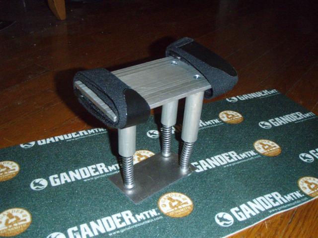
The idea behind the Moonwalker was to create a strap-on shoe accessory that would allow the user to jump higher and walk as if they were on the moon. The Moonwalker employs the use of springs on the bottom of a platform to create this feel. Due to cost and manufacturing time, the prototype was scaled down and the adjustable sizing feature was eliminated.
Design Process
All the components, except the springs, straps, and screws, were machined out of alluminum using the mill, lathe, abnd saw and taps.
The Moonwalker is constructed out of the following parts:
The fist step was to make the top base, which was cut from a larger piece of alluminum with the band saw and then milled to get two sets of parallel edges. Once that was done, centers of where the three tubes (we decided to add a third spring for stability after our presentation) were placed and a clearance hole was drilled and counter sinked this was so screws could be used to attach the tubes to the base. Only one screw was used, which does not prevent the tube from rotating, so in future models two or more screws should be used.
Next the the top flanges were lathed into a circular step pyramid. The first step was just under the inside diameter of the tube (0.6 in), and the second step was just over the inside diameter of the spring (0.35in). Once that was achieved and both sides of the flange were smoothed out, a hole in the top side was drilled with the lathe and then tapped for the screw going through the top base. Next the flange was brough to the mill where a hole was drilled horizontally through the flange. An edge finder was used to fing the percise spot the hole would be made. This hole was also tapped for the screw that would come through the tube, and attachinf the tube to the base.
Next the tubes were machined. First three rough cuts were made with the band saw and then the cuts were smoothed out using the lathe and then cut to size using the lathe. Once this was done a clearance hole was drilled horizontally using the same method as above through one side of the tube for the screw.
With these three parts done the top assemblye was now complete.
For the bottom assembly, first the feet (aka bottom flanges) were machined using the lathe with the same idea as the top flange, just with one step (for the inside diameter of the spring) and no horizontal hole was drilled.
Then a bottom base was created using the same method as the to base to connect the feet to one plane.
Assembly
All parts were screwed together, except for the springs, which just had friction between them and the flanges holding them in place.
Design Issues and Improvements
The first issue that cam up before production was that our design was too complicated. Since the main idea and hardest component was the spring mechanism, the prototype was to focus on this and the adjustable sizing mechanism was left out all together and replaced by two straps at either end of the Moonwalker. Two issues came up during the machining process: 1. How to attach the springs and 2. Keeping the springs form deflectingoutside the vertical axis. In the original design there was going to be a tube inside the spring with a slot and a pin between the inner and outer tubes, preventing the spring from falling out. Sonce the prototype was scalled down, this was out of the question, so at first a cable or rubberband running between the two flanges was the plan, but that also was not possible, so the solution was to have the flanges just larger than the inside diameter and use friction to hold the springs to the flanges. For the second issue, when weight was put on the Moonwalker the springs tend to bend rather than compress in all different directions. Because of this, a bottom base was made to connect the three feet, this prevents the bending in all different directions, but does not prevent bending - a tube inside the spring is needed to do this.