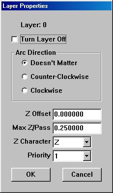
The Layer Dialog Box
The layer dialog box is accessible by double-clicking on the on any
one of the layers listed in the layer column of the ACEconverter window.
This means, of course, that a DXF file must be loaded into ACEconverter
before accessing the Layer dialog box.
This dialog allows the user to:
-
Turn the layer off. If this box is checked, no entities in this layer
will be converted.
-
Determine which direction to cut arcs and circles in this layer.
If "Doesn't Matter" is selected, upon priority optimisation the direction
of each arc or circle will be automatically generated and optimized if
the priority the layer belongs to is optimized. Otherwise, the arcs and
circles default direction is counterclockwise.
-
Set the Z offset of the layer. This setting just offsets the value
of all Z values by the number specified. So if the drawing was made
on the XY plane located at Z=0, the user could change this plane to be
any Z value.
-
Set the maximum depth per pass. This setting allows the user to determine
if more than one pass needs to be made during the machining process.
So for example, if your tool path is drawn at Z=-0.8 and the Max Z/Pass=0.25,
then there would need be 4 passes generated in order the get to the proper
Z depth of -0.8.
-
Determine the character to be used in place of the Z character in the DXF
file. This can be very useful in 4 axis operations. So for
example, if the user's fourth axis is named W, this character can be set
to W and this layer would be generated only for the fourth axis control.
This effectively allows the user to integrate his or hers fourth axis into
tool path code yet not lose optimization by doing so.
-
Determine which Priority the layer belongs to. Each layer belongs
to a priority. The priority properties define the layer properties
further.
Back To ACEconverter Help Index