Step-By-Step Manufacturing Instructions
- Aquire Materials:
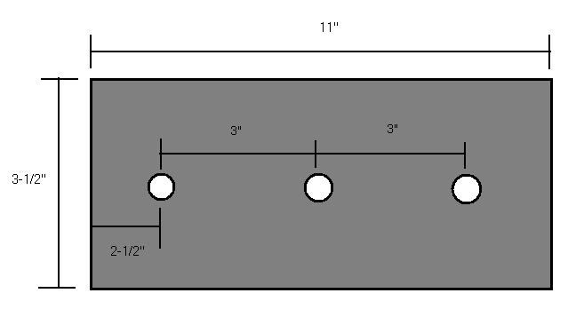
- 1/4" Aluminum plates (11" by 3.5") (2)
- 3" diameter machining Plastic cylinders (need at least 10-12")
- 1/2" aluminum rods (at least 20")
- hex screw 1/2" shaft colars (9)
- 1/8" sheets of acrylic plastic sheets (2)
- Small rectangle of thin aluminum to attach motor
- 4 small bolts and 4 nuts
- small piece of 1/4" plastc to house motor
- Rubber bands for tires
- 24V motor with planetary gear system
- 2 tought pulley bands
- gears/ belt assembly for motor
- Machines needed:
- Lathe
- Drill Press
- Band Saw
- Milling Machine
- Laser cutting machine
- Maching Process:
- Take Aluminum plates and mill sides plates to make flush sides.
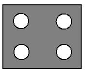
- Drill 5/8" holes in the plate according to diagram:
- Repeat this process with the second side
- Now time to create the gear ration sections with the cylinder of machining plastic
- Cut the plastic into 3, 4" cylinders and place on lathe
- Lathe the cylinder to the following diagram:
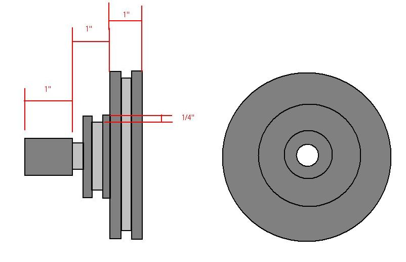
- Band saw the remaining block of one inch off so that the gear will be 3" long.
- Drill a 1/2" hole on the center of the 1" gear side (through all)
- Repeat this 3 times
- With the aluminum shafts, cut 2 5" lengths and one 6 inch length (the longer one is used for the driving shaft which is attached to the motor).
- Draft up 4-1/2" or 5" inch circular wheels on CAD software(feel free to add any rim details).
- Make sure to have just slightly more than a 1/2" hole in the center of the wheel (to attach and spin freely on shaft)
- Upload wheel files into laser cutting software.
- Laser cut 8 circular wheels, and glue a pair together to make wheel 1/4" thick (should end up with four wheels)
- Stretch 4 rubberbands and place over the outside edge of each wheel (will be used for traction)
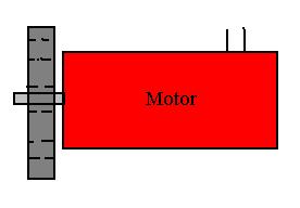
- Now its time to make the motor mount.
- Take small sheet of aluminum and drill 4 holes close to each corner (the holes should be big enough for the bolts and nuts to fit flushly)
- Attach motor to small piece of plastic (drive shaft should be able to stick through the plastic
- Assembly:
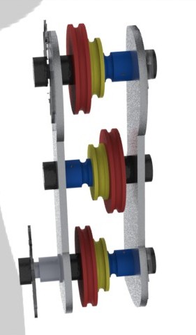
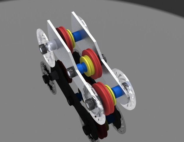
- Slip the gears onto middle of the aluminum shafts ( they should fit snug and not move freely)
- Attach a shaft color behind the 3" diameter of two of the shafts.
- Take the shafts and gears and fit them into the holes in one one of the aluminum side plates.
- Alter nate the gears like so:
-
- Pull tought pulley belts over shafts and leave loose on the gears (one should be over the first and second gear, and one should be over the second and third)
- Drill holes in other siding (same size as small aluminum plate with nuts and bolts) inconvient place on back of side in order to fit the desired driving impliments (gears and or pulley motor-to-wheel assembly)
- Place other aluminum side over the shafts.
- Attach wheels on the first and third shaft.
- The side with the longer shaft will have the motor and free spinning wheels.
- On the side opposite the motor side, glue the wheels to the shaft and make sure they do not free spin.
- Attach the rest of the shaft collars on the remaining lengths of the shafts in order to keep wheels and sidings in place.
- Attach desired motor driving system with nuts and bolts (use small aluminum plate to attach plastic motor mount and motor)
- Finally attach a battery source and try switching around gear ratios for desired effect of either speed or torque.
Enjoy!