JP System 5
Manufacturing Process
-
Reference the manual that accompanies
the JP System package for thorough step-by-step instructions.
-
Design a part in a standard CAD
program.
-
Export part as an .stl file into
JP 5 software.
-
Orient the part along the positive
axes so that the largest cross section is at the top of the part.
-
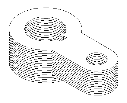
Slice the design with the JP software.

-
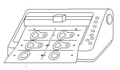
View the layout (as shown in picture) and send the data
to the cutter. Each sheet may contain multiple slices. When
these are stacked they will form sub-parts of the final prototype.

-
Feed the paper into the cutter
as necessary.

-
Align the first sliced sheet on
the registration board with the adhesive side down and tape it top the
board.

-
Spray adhesive on the first sheet.
-
Remove any sliced sections of
the sheet enclosed by the prototype that will not be part of the prototype.
-
Stack the rest of the sliced sheets
in order, adhesive side up, and remove the backing as well as all excess
paper before adding the next sheet.

-
As the prototype gets taller may
be necessary to add spacers to the registration board to ensure proper
alignment. See manual for a further explanation of spacers.
-
Remove the adhesive backing of
the sub-parts and stack them together to form the prototype.
-
Coat any rough edges with Elmer's
glue to smooth them out. Let the glue dry.
-
Coat the whole prototype with
a clear polyurethane spray.
-
Pat yourself on the back.
You are done.
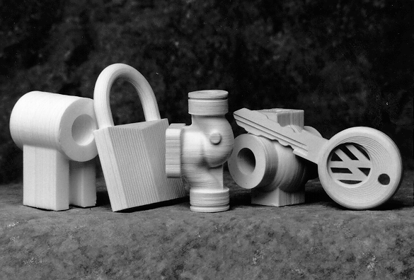
Finished products can look like this:

Back to main page


