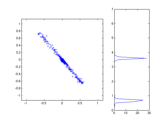
We have seen that edges and other features in the image lead to
recognizable patterns in the surrounding image gradient
vectors. For example, an edge or line in the image causes an
elongated shape in the plot of gradient vectors, corresponding to a
single dominant orientation or two dominant orientations separated by
180 degrees. On the other hand, a corner, cross, or highly
textured region causes a more rounded shape, corresponding to at least
two dominant orientations pointing in different directions.

We can design edge detectors and corner detectors to take advantage of
these differences. The most common edge and corner detectors are
based on the so-called "image structure matrix," which we will describe
next.
The image structure matrix captures the dominant orientation of a set
of gradient vectors, and also the average length of the gradient
vectors, both
along the dominant orientation and perpendicular to the dominant
orientation. The image structure matrix for a local region is
based on the single-pixel image structure matrix, which is
defined as:
where gx is the x gradient of the image intensity at a given pixel and
gy is the y gradient. Another way to write this matrix is (g g')
where g=(gx, gy)' is the gradient vector.
Of course, at a single pixel there's only one gradient vector, and we
want to measure the properties of the set of gradient vectors near a
pixel. So, to get the local image structure matrix, we will
average the one-pixel image structure matrix for all of the pixels in a
local region. (Averaging a matrix means averaging each component
separately.) We can find the components of the image structure
matrices efficiently for an entire image by computing, e.g., gx*gy for
all pixels in the image and then applying a smoothing filter such as a
box filter or a Gaussian filter to the gx*gy values.
The dominant direction d in a local region is the one such that d'g is,
on average, as big as possible. We are not distinguishing between
light-to-dark and dark-to-light edges, so we will maximize the average
of (d'g)^2. But
(d'g)^2 = (d'g)(g'd) = d'(gg')d
The average of d'(gg')d is just d'Sd, where S is the image structure
matrix. So, we want the direction that maximizes d'Sd. More
precisely, we want to normalize for the length of d (otherwise we could
make d'Sd as big as we wanted by scaling d). So, we will maximize
d'Sd / d'd
This expression is called the Rayleigh quotient of S, and the direction
d which maximizes it is the dominant eigenvector of S. (See here for more information about
eigenvectors.) The strength of the edge in this direction (that
is, the value of (g'd)^2) is
given by the dominant eigenvalue of S.
So, one common edge detector is to test the size of the larger of the
two eigenvalues of S. If we write the components of S as
then the larger eigenvalue is (ignoring constant factors)
(a+d) + sqrt((a-d)^2 + 4b^2)
The smaller eigenvalue of S corresponds to the length of the gradient
vectors in the direction perpendicular to d. Since corners have
significant edges in two nearly-perpendicular directions, a common
corner detector is to test the size of the smaller eigenvalue of
S. This eigenvalue is (ignoring constant factors)
(a+d) - sqrt((a-d)^2 + 4b^2)
Another common pair of edge and corner detectors looks at the sum and
product, respectively, of the two eigenvalues of S. The sum of
the eigenvalues is (ignoring multiplicative constants)
a+d
and the product is
ad - b^2
These expressions are simpler to compute than the eigenvectors
themselves (for example, they do not require any square roots), and
they result in similar edge and corner detections.
Here are the edges from the sum-of-eigenvalues detector:
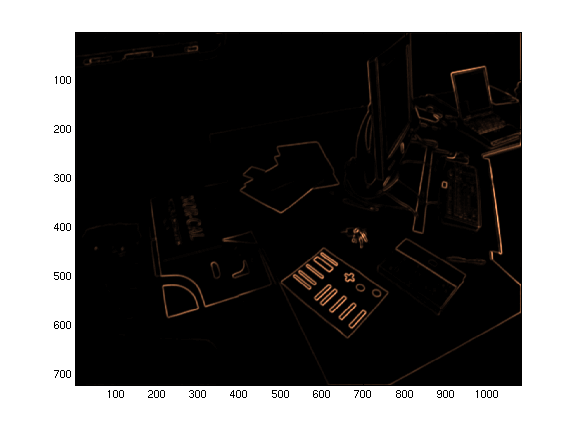
And here are the corners from the product-of-eigenvalues detector:

In both cases the image gradients were computed with 7 x 7
derivative-of-gaussian filters, with a sigma of just less than one
pixel.