|
|
|
Sketch<uchar>.
Following the convention we established for sketches, we'll use the
lowercase term "shape" to refer to actual shapes, and the capitalized
term Shape to refer to a smart pointer to one of those shapes. Blobs
are described by BlobData objects, and smart pointers to blobs are
called Shape<BlobData>. Blobs are one of several types of
shapes supported by Tekkotsu. Their names all end in "Data", and they
are all children of the BaseData class. Here is a list:
Extracted shapes live in a ShapeSpace, which is the dual of the SketchSpace they came from. For the camera sketch space camSkS, the dual space is called camShS.
Basic shapes: PointData, LineData, EllipseData Complex shapes: PolygonData, BlobData, MarkerData 3-D shapes: SphereData, BrickData Robot shape: AgentData (robot position and orientation on the world map)
#include "Behaviors/StateMachine.h" |


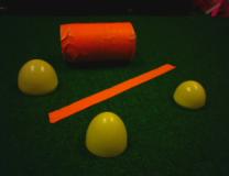
Note that within each color class, the blobs with the greatest area are extracted first. This does not necessaily mean the largest bounding box. For example, the diagonal orange line 10002 has a larger bounding box area than the cylinder, but the latter has more pixels, and is therefore extracted first.Id: 10001 Color: [245,113,65] Area: 1968 Id: 10002 Color: [245,113,65] Area: 1176 Id: 10003 Color: [245,113,65] Area: 129 Id: 10004 Color: [186,167,12] Area: 1316 Id: 10005 Color: [186,167,12] Area: 990 Id: 10006 Color: [186,167,12] Area: 631
We don't normally work with LineData objects directly. Instead we use the smart pointer
Length Distance between endpoints; ignores valid/active flags. Orientation Since lines are symmetric, orientations range between 0 and pi. The slope is the tangent of the orientation. Normal vector (rho,theta) This is the endpoint of a vector from the origin that intersects the line at a right angle. It is expressed as a distance rho (always positive) and an angle theta (0 to 2 pi).
Shape<LineData>. Smart pointers
provide reference counting and validity checking.
Shape<LineData> overloads the -> operator so that
successfully dereferencing it gives you access to the LineData's
member functions.
The line extraction functions return a
vector<Shape<LineData> >. (Note that
the space between the two greater-than signs is required for C++ to
properly parse the expression.) There are currently two line
extraction methods available: one based on moments, and one using the
Hough transform.
$nodeclass DstBehavior : VisualRoutinesBehavior : doStart { |


Here is an example of marking the leftmost point of a line. We use a
leftPt(), rightPt() leftPt() returns the leftmost of the two endpoints based on their X coordinates; rightPt() returns the rightmost. If the line is vertical the choice is arbitrary, but the two functions will always return different endpoints. topPt(), bottomPt() topPt() returns the topmost of the two endpoints based on their Y coordinates (smaller values = topmost); bottomPt() returns the botommost. If the line is horizontal the choice is arbitrary, but the two functions will always return different endpoints. leftPtShape(), rightPtShape(), topPtShape(), bottomPtShape() These functions return a Shape<PointData> instead of a raw EndPoint. The parent is set to the line object. isHorizontal(),
isVertical()A line is considered to be horizontal if its slope is no greater than 60 degrees; it is vertical if its slope is no less than 30 degrees. Diagonal lines (slopes between 30 and 60 degrees) satisfy both predicates. firstPt(), secondPt() If the line satisfies isHorizontal(), its first point is the leftmost endpoint. Otherwise its first point is the topmost endpoint. The second point is defined similarly. firstPtShape(), secondPtShape() Returns the first or second point as a Shape<PointData> rather than a raw EndPoint. firstPt(otherline), secondPt(otherline) These functions are useful when comparing two lines that might be just on the cusp of satisfying the horizontal test; hence one could pass the test while the other fails. To enforce agreement, we use one line to make the horizontal/vertical decision for both. If otherline satisfies isHorizontal(), this line's first point is the leftmost endpoint; otherwise this line's first point is the topmost endpoint. The second point is defined similarly.
Shape<PointData> to represent the point.
$nodeclass DstBehavior : VisualRoutinesBehavior : doStart {
  NEW_SKETCH(camFrame, uchar, sketchFromSeg());
  NEW_SKETCH(orange_stuff, bool, visops::colormask(camFrame,"orange"));
  NEW_SHAPE(line, LineData, LineData::extractLine(orange_stuff));
  NEW_SHAPE(leftpt, PointData, line->leftPtShape());
  leftpt->setColor("green");
}
|
orange_stuff sketch so we can
superimpose the line on top of it.

$nodeclass DstBehavior : VisualRoutinesBehavior : doStart { |


$nodeclass DstBehavior : VisualRoutinesBehavior : doStart {
  NEW_SKETCH(camFrame, uchar, sketchFromSeg());
  NEW_SKETCH(orange_stuff, bool, visops::colormask(camFrame,"orange"));
  NEW_SHAPE(line1, LineData, LineData::extractLine(orange_stuff));
  line1->leftPt().setActive(false);
  NEW_SHAPE(line2, LineData, new LineData(camShS,line1->rightPt(),line1->getThetaNorm()));
  NEW_SKETCH(corner, bool, visops::seedfill(line1->getRendering() | line2->getRendering(), 0));
  corner->setColor("green");
}
|


Shape<EllipseData> can be used to describe circular
or elliptical shapes. This differs from blobs in that the
EllipseData::extractEllipses function will reject regions that are not
roughly elliptical. Also, EllipseData calculates semimajor and
semiminor axis lengths, and the axis orientation, which only makes
sense for ellipses.
$nodeclass DstBehavior : VisualRoutinesBehavior : doStart {
  NEW_SKETCH(camFrame, uchar, sketchFromSeg());
  NEW_SKETCH(orange_stuff, bool, visops::colormask(camFrame,"orange"));
  NEW_SKETCH(yellow_stuff, bool, visops::colormask(camFrame,"yellow"));
  NEW_SHAPEVEC(ellipses, EllipseData, EllipseData::extractEllipses(yellow_stuff));
  NEW_SHAPEVEC(ellipses2, EllipseData, EllipseData::extractEllipses(orange_stuff));
}
|

A->copy() returns a new shape
pointing to a deep copy of shape A, i.e., a new instance of LineData,
EllipseData, etc.
|
|
|
 using namespace DualCoding;
$nodeclass DstBehavior : VisualRoutinesStateNode : doStart {
NEW_SKETCH(camFrame, uchar, sketchFromSeg());
NEW_SKETCH(orange_stuff, bool, visops::colormask(camFrame,"orange"));
NEW_SHAPEVEC(blob_shapes, BlobData, BlobData::extractBlobs(camFrame,100));
NEW_SKETCH(blob0, bool,
blob_shapes.size() > 0 ? blob_shapes[0]->getRendering()
: visops::zeros(camFrame));
SHAPEVEC_ITERATE(blob_shapes, BlobData, myblob)
cout << "Id: " << myblob->getId()
<< " Color: " << myblob->getColor()
<< " Area: " << myblob->getArea()
<< endl;
END_ITERATE;
}
using namespace DualCoding;
$nodeclass DstBehavior : VisualRoutinesStateNode : doStart {
NEW_SKETCH(camFrame, uchar, sketchFromSeg());
NEW_SKETCH(orange_stuff, bool, visops::colormask(camFrame,"orange"));
NEW_SHAPEVEC(blob_shapes, BlobData, BlobData::extractBlobs(camFrame,100));
NEW_SKETCH(blob0, bool,
blob_shapes.size() > 0 ? blob_shapes[0]->getRendering()
: visops::zeros(camFrame));
SHAPEVEC_ITERATE(blob_shapes, BlobData, myblob)
cout << "Id: " << myblob->getId()
<< " Color: " << myblob->getColor()
<< " Area: " << myblob->getArea()
<< endl;
END_ITERATE;
}
 NEW_SKETCH(camFrame, uchar, sketchFromSeg());
NEW_SKETCH(pink_stuff, bool, visops::colormask(camFrame,"pink"));
NEW_SHAPEVEC(lines, LineData, LineData::extractLines(pink_stuff));
}
NEW_SKETCH(camFrame, uchar, sketchFromSeg());
NEW_SKETCH(pink_stuff, bool, visops::colormask(camFrame,"pink"));
NEW_SHAPEVEC(lines, LineData, LineData::extractLines(pink_stuff));
}
