2.0 System Decomposition
2.1 System Decomposition
The OWL system is broken down into eight separate subsystems: Control, Database,
Facility Mangement, Notification, Simulation, Site Editor, User Interface
and Visualization.
The subsystems communicate with each other through an implementation of
the CORBA software bus developed by Iona called CorbixWeb. CorbixWeb allows
subsystems to access objects from other subsystems and remotely call methods
of those objects.
One of the two main purposes of the Control Subsystem is to read data from
the sensors, and to pass the information received from the sensors to the
database. The other activity of the Control Subsystem is to provide an interface
for the shades, louvres, and other light manipulation devices. Extensibility
for temperature control and other sensors is included in the design models
so it can be added in the future.
The Database Subsystem provides services for storage
and retrieval of any persistent data in the OWL project. These services
are provided through a CORBA interface. This subsystem will behave as a
server in most instances. Other subsystems will call the public methods
of Database Subsystem and process the returned data. The only client behavior
will be in the form of data triggers. An example of a data trigger is as
follows:
When the Facilities Manager updates the floor
layout in the site editor and commits the updated layout to the database,
the database will announce (via the notification sytem) that the layout
has been altered. The Visualization subsystem, for example, will react
to that notification by retrieving a new copy of the layout and rebuilding
its VRML model.
In addition, the Database group will provide a
minor subsystem which will retrieve weather forecast data from the Internet
and store it for later retrieval. This subsystem will behave as a client
in two client/server relationships. The first relationship is between a
weather information server and the subsystem. The subsystem will query
that server and retrieve a weather forecast. The second relationship is
between the subsystem and the database server. The subsystem will store
the retrieved weather forecast in the database by calling a public method
on the Database Subsystem.
The Facility Management Subsystem (FMS) is meant to assist Facility Managers
with modifying floorplans, scheduling room reservations, and maintaining
inventory control information.
To do this task, the FMS will be interracting with UI in a client/server
relationship, with the FMS being an information provider and providing a
CAD tool to allow Facility Managers to modify floorplans.
The FMS will also be interacting with the Database subsystem in a client/server
relationship. The Database subsystem will be taking care of all the FMS's
long term data storage needs. There is some interaction between the FMS
and the Control Subsystem, this will be clairified in the near future.
Within the FMS there are two major divisions: the reservation facility and
the controls for building editing and inventory control. The reservation
facility is a facility that provides the ability to schedule reservations
in rooms. The controls for building editing and inventory control provide
and interface to allow modifications to the building, and since the act
of moving items is close to inventory control, it has been decided to group
these two into one facility. These two facilities interact based upon the
creation and deletion of rooms which allow reservations.
A final division is outside the FMS proper: a CAD tool interface. This tool
is something needed by multiple groups (FMS and Simulation) to access the
CAD tool. This interface is used by the controls for building editing and
inventory control.
The Notification Subsystem provides the service of notifying other subsytems
when an event has occurred. The subsystems can create events, subscribe
to an event and notify other subsystems when an event has occurred. The
implementation of the Notification Subsystem will use a previously implemented
notification system based on either the COSS Event Server from Iona or a
similar subsystem used for the JEWEL System.
The Notification Subsystem is always a server to the other subsystems and
only calls another subsystem when an event has occurred which that subsystem
has subscribed to.
The Simulation Subsystem provides a service through which simulations can
be run on a site. Currently design is only for an interface to a pair of
existing simulators, however the design is easily expandable
to include other simulators as they become available.
The Site Editor Subsystem is a CAD tool used by the Facility Management
Subsystem and the Simulation Subsystem. The CAD tool is Microstation. The
Facility Management Subsystem uses the Site Editor to change floorplans.
The Simulation Subsytem uses the Site Editor to edit the floorplan and
attributes of a site (such as the Intelligent Workplace) which influence
the results of the simulations.
The Site Editor is a server to the User Interface. Simulation and Facility
Management provide server functionality to the Site Editor.
The User Interface Subsystem is responsible for providing the means of communication
between the OWL system and the users of the system. The design is aimed
towards the goal of having multimodal input (speech and gesture as well
as mouse and keyboard).
The visualization subsystem provides a three-dimensional interface to the
Intellegent Workplace, which runs inside of the user interface subsystem.
It recieves some model of the current Intellegent Workplace layout, which
is stored in the system database in some generic format, and converts it
into VRML 2.0 for display using a Liquid Reality browser. In addition it
will send some signal to the user interface subsystem if the user enters
or leaves a room.
This subsystem has a peer-to-peer relationship with the user interface subsystem.
This is becuase it will recieve input from the user via the user interface
subsystem, and it will notify the user interface subsystem about user actions
and position. At the same time, it will have a client-server relationship
with the database subsystem. Their interaction is restricted to the database
replying to data requests from the visualization subsystem.
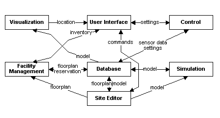
Summary of Communication Relationships
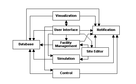
Figure 2.1.1: Communication Relationships between the subsystems. The
tail represents the client side of the relationship and the head the server
side. A two-headed arrow indicates a peer-to-peer relationship
2.1.1 Layers & Partitions
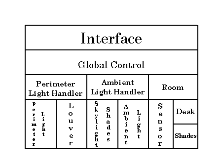
Figure 2.1.1.1: Control Subsystem Structure
The Control Subsystem depends on the Database Subsystem for the default
and user defined lighting levels. The Facility Management subsystem depends
on the Control Subsystem for maintaining the required levels. The Control
Subsystem depends on the User Interface Subsystem for the new lighting levels.
The Database Subsystem depends on the Control Subsystem for providing it
with the new lighting levels that originated from the User Interface Subsystem.
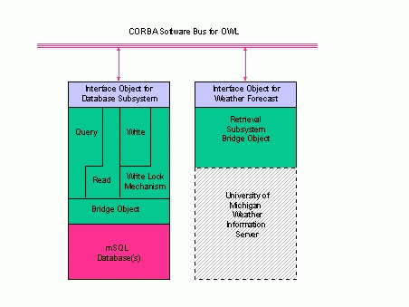
Figure 2.1.1.2: Database Team Layers
The Database team is responsible for two subsystems,
the Database Subsystem and the Weather Forecast subsystem. The layering
of the Database Subsystem is as follows:
- The Interface Layer (light blue) consists
of all public methods on the Database Subsystem. This object uses CORBA
to interface with the rest of the OWL system. This includes accepting requests
as well as providing notifications of data triggers.
- The Implementation Layer (green) consists
of implementations of the public methods and a Bridge Object to interface
with the database engine. This layer is subdivided into two layers and
four partitions.
- Method partitions are not strictly partitions, but a combination
of partitions and layers which enable the desired functionality of the
subsystem.
- The Query partition implements the query method
of the subsystem. It may return tags of the data items which match the
query, or it may read each data item and return the items directly.
- The Read partition handles a read of a specific
data item as described by a unique identifier.
- The Write partition handles a write of a specific
data item as described by a unique identifier or a new data item. It must
go through the Lock Mechanism first.
- Lock Mechanism partition implements write locks
to maintain consistency on very specific data items under special circumstances.
- The Bridge Object is a design pattern which allows
the underlying implementation of the database engine to change without
effecting any other part of the database system. In the future, if mSQL
is found to have insufficient performance, a different database could be
added or used instead. The only subsystem modifications would occur in
the Bridge Object.
- The Database Engine Layer (red) includes
the chosen database engine an any support code required to keep it running
properly.
The layering of the Weather Forecast subsystem
is as follows:
- The Interface Layer (light blue) consists
of a CORBA interface which allows the subsystem to write to the database.
- The Implementation Layer (green) consists
of a Bridge Object to interface with any weather information service.
- The Weather Information Service Layer
(dashed grey) is any specific weather information server. A specific example
is sprl.umich.edu.

Figure 2.1.1.3: Facility Management Subsystem Structure
The FMS depends on the existance of the database server, and will await
the return of the database server, should that server ever be unreachable.

Figure 2.1.1.4: Notification Subsystem Structure
The Notification Subsystem does not depend on any other subsystem. However,
if there are no other subsystems then Notification has nothing to do. It
is a basic service for all other subsystems.
This subsystem is simply an interface added on top of existing code. It
has yet to be determined whether that existing code will be an implementation
of the COSS Event Server created by Iona or a notification subsystem used
for the JEWEL System.
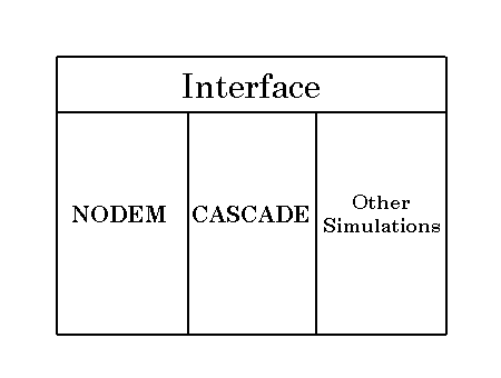
Figure 2.1.1.5: Simulation Subsystem Structure
The Simulation subsystem is an interface to external simulators. Currently
there are only two existing simulators (called NODEM and CASCADE). The only
subsystems which are depended on by the Simulation Subsystem are the Site
Editor which allows changes to be made to the model that is used in the
simulation and Database which provides the models for the simulation.
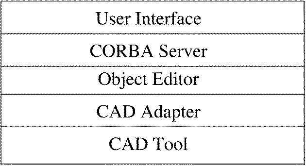
Figure 2.1.1.6: Site Editor Subsystem Structure
The Site Editor Subsystem depends on both Simulation and Facility Management.
The models which are edited through Microstation are provided through those
two subsystems.

Figure 2.1.1.7: User Interface Subsystem Structure
The User Interface Subsystem depends on Visualization to determine the
location of the user when they are using the 3 Dimensional Interface.

Figure 2.1.1.8: Visualization Subsystem Structure
The visualization subsystem dempends on two other subsystems. It depends
on the Database Subsystem for the object model of the Intellegent Workplace,
and User Interface subsystem for user input. At the same time, the User
Interface Subsystem depends on visualization to tell it when a user enters/leaves
a room.
2.1.2 System Topology
The information flow in the system is implemented using Java interface objects
interconnected through CorbixWeb (an implementation of CORBA).
Data Flow Diagram
Example Scenario:
The Liquid Reality browser sits upon a graphics library and the java virtual
machine. Inside when the user requests to view the three dimensional model,
several stubs are called. One will be dedicated to the walls, one to the
furnature, etc., decomposing the system by parts of the Intellegent Workplace
model. Each of these stubs connect to a geometry server which keeps a cached
copy of the current model in memory. The geometry server checks the database
periodically and re-caches the model if it has changed. If the model has
changed in the database, the geometry server calls a thread to generate
the VRML text for the objects requested by the client. If the model hasn't
changed, the geometry server sends the cached VRML representation of the
requested objects back to the client.
 Return to the main System Document Page