Surfaces and Hinges
Dave Touretzky
Klein Bottle
Source: https://www.youtube.com/watch?reload=9&v=MpfFYe0OGg4


- Start a new part with units MMGS.
- Go to View > Hide/Show and turn on Sketch Relations.
- Make a new sketch on the Front plane.
- Draw a vertical centerline upward from the origin.
- Dimension the centerline to 160 mm.
- Draw a two-point spline from the top to the bottom of the centerline.
- Grab control points and bow out the spline to the right.
Dimension the angle of the top control point to 45 degrees by
clicking on the diamond and then clicking on the centerline.
- Dimension the length of the top control point to 300 by clicking
on the arrowhead.
- Click and drag on the bottom control point so that relations appear
in the dialog box at left, and add a Horizontal relation.
- dimension the length of the bottom control point to 200.
- Add two horizontal construction lines running from the centerline to the spline.
- Dimenson top construction line to 30 mm and the bottom one to 40 mm.
- Exit the sketch.
- Make a new sketch on the Front plane by clicking on Front Plane
in the feature manager tree and then clicking on the New Sketch
shortcut.
- Click on all four items in the firt sketch and do Convert Entities.
- Trim away everything above or below the horizontal construction
lines, and the horitzontal lines themselves.
- Change the vertical line to a construction line.
- Exit the sketch.
- With the new sketch selected, go to the Surfaces tab and click Revolved Surface.
- Click on the green checkmark to complete the feature.
- Hide Sketch 1.
- Make a new sketch on the Front Plane.
- Select 3-point arc.
- Put the first point vertically above the midpoing of the top edge
of the revolved surface.
- Put the second point well to the left of the first.
- Put the third point high enough so that the arc forms a semicircle.
- Select the two endpoints and the center point of the arc and add
Horizontal relations between them.
- Select the right point of the arc and the origin and add a Vertical relation.
- Dimension the distance between the top point of the arc and the
origin to 210 mm.
- Dimension the distance between the arc centerpoint and the right
point of the arc to 30 mm.
- Now the arc should be fully defined.
- Add a two-point spline from the left edge of the arc to a point
on the midline above the origin.
- Dimension the distance from the spline end point to the origin to 35 mm.
- Bend the top control point leftward and the bottom control point rightward.
- Add vertical relations to the top and bottom control points.
- Dimension the top control point to length 150 mm.
- Dimension the bottom control point to length 200.
- Exit the sketch.
- Select a Swept Surface feature and switch to a circular profile
with diameter 25 mm.
- Select the spline as the path.
- Click on the green checkmark to copplete the feature.
- Select a Lofted Surface feature.
- Select the edge of the swept tube and the top edge of the
revolved surface as the profiles.
- Line up the green balls to make a straight line.
- Open the Start/End Constraints and set the start constraint to
Tangency to Face. Set the strength to 1.5.
- Set the End Constraint to Curvature to Face and the length to 0.75.
- Click on the green checkmark to complete the feature.
- Using the button at the top of the graphics window, change to a
Hidden Lines Visible view.
- Start a Lofted Surface feature.
- Select the bottom edge of the rube and the bottom edge of the
revolved surface as the profiles.
- Move the green balls to the left edge of each profile.
- Set the Start constraint to Tangency to Face with length 3, and
the End constraint to Tangency to Surface with length 10.
- Click on the green checkmark to complete the feature.
- Use the button at the top of the graphics window to switch the
view back to Shaded.
- Start a Cross Section view.
- Insert a Knit Surface feature and knit together the three
surfaces that are not the tube.
- Insert a Split feature by typing "Split" in the search box at the
top of the window.
- Select the tube as the trim tool.
- Click on Cut Bodies.
- Select Body 1 in the Resulting Bodies list.
- Click the green checkmark to complete the split.
- Insert a Delete/Keep Body feature.
- Under Bodies to delete, select the Split surface.
- Click on the green checkmark to complete the operation.
- Insert a Thicken surface feature to thicken the knit surface.
- Select the "both sides" option and set the thickness to 1 mm. Turn on Merge result.
- Thicken the tube the same way.
- Insert a Fillet feature and set the radius to 5mm.
- Fillet the outside and inside edges where the tube crosses the
knit surface.
- Play with the cross section view to get different views of
the Klein bottle.
- Click on the Apply Scene button along the top edge of the
graphics window to try different scenes, such as Rooftop.
- Try changing the material to Brass.
Using Trim Surface
Source: https://www.youtube.com/watch?v=9s4AuFBVa1M

- Start a new part with units MMGS.
- Switch to the Surfaces tab and make a Revolved Surface.
- Select the Front plane.
- Draw a horizontal line extending from the origin to the right.
- Draw a diagonal line extending from the right edge of the horizontal line, up and to the right.
- Add a vertical centerline extending up from the origin.
- Dimension the angle between the centerline and the diagonal line to 10 degrees.
- Select the Smart Dimension tool, click on the centerline, then
click on the right edge of the horizontal line and drag the dimension
tool over to the left until you are dimensioning the distance between
the line endpoint and the symmetric point on the other side of the
horizontal line. Set this distance to 70 mm.
- Dimension the top of the diagonal line to be 100 mm vertically from the origin.
- Exit the sketch and complete the Revolved Surface feature.
- Start a new sketch on the Front plane.
- Start a 3-point arc. The first point should be on the bottom
edge of the surface, near the right edge. The second point should
be to the right of the top edge of the surface. The third point
should be somewhere between the first two, inside the surface.
- Add a Coincident relation between the top point of the arc and the top edge of the surface.
- Add a vertical centerlin to the right of the arc.
- Dimension the horizontal distance from the centerline to the origin to 120 mm.
- Dimension the horizontal distance from the centerline to the
bottom point of the arc to 90 mm.
- Dimension the arc radius to 200 mm.
- Make the centerpoint of the arc Horizontal with the origin. Now everything should be fully defined.
- Exit the sketch.
- Set the revolution angle to 45 degrees and change the direction from Bline to MidPlane.
- Click on the green checkmark to complete the feature.
- Switch to the Features tab and create a Circular Pattern feature.
- Set the direction parameter to the cylindrical surface.
- Close the Features to Pattern and open Bodies to Pattern.
- Select the patch surface as the body to pattern.
- Set the number of copies to 5.
- Complete the circular pattern.
- Go back to the Surfaces tab and select Trim Surface.
- Set the trim type to Mutual.
- Set the surfaces to the cylinder plus each of the 5 patches. You
can't just select the Circular Pattern once; you have to click on all
5 patches individually. One will be a Revolved Surface and the other
four will be Circular Pattern instances.
- Choose Keep Selections.
- Set the view to show Excluded bodies. That's the only view in which you'll
be able to click on bodies to keep.
- Click on the tumbler body, then click on the five panels in the interior of the tumber. As you click on a body it will disappear
from the view, except the embossed panels won't seem to disappear because
there is a tumbler body region almost on top of them. But if you switch temporarily to the
Included bodies view you will see what's really being included.
- Click on the green checkmark to complete the trim.
- Color the part orange.
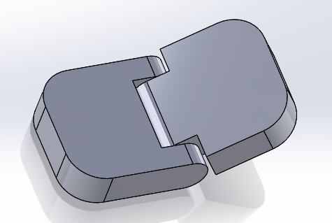
3D-Printable Hinge
Adapted from https://www.youtube.com/watch?v=UvY4laqJZPM
- Start a new part with units MMGS.
- Make an Extruded Base on the Front Plane.
- Draw a horizontal rectangle to the left of the origin, so that its bottom right point is the origin.
- Draw a small circle centered on the midpoint of the right edge of the rectangle.
- Add tangent relations between the circle and the top and bottom
lines of the rectangle.
- Dimension the rectangle to have width 15mm and height 5 mm.
- Trim away the right edge of the rectangle and the left half of the circle,
leaving a single closed contour.
- Make two concentric circles centered on the same point as the semicircle.
- Dimension the outer circle to 3.5 mm.
- Dimension the inner circle to = [outer circle dim] - 0.6. Note that this sets up an equation for the inner circle dimension.
- Add a vertical line connecting the top and bottom lines, 12mm in
from the left edge, and dimension the distance. Note that thsi is not a construction line.
- Extrude to a depth of 3mm. Select all four bodies for extrusion.
- Flip the part around and make Sketch1 visible.
- With Sketch1 selected, do another Extruded base in the oppostie
direction, set the depth to 5mm, and select only the rectangle and
inner shaft to extrude.
- Make a plane coincident with the flat surface of the rectangle, and name it MidPlane.
- Insert a Mirror feature, choose Midplane as the mirror plane,
select the two extruded bases as the features to mirror, and turn on
Geometry Pattern.
- Add a Fillet with radius 4.5mm to the back corners of the rectangle.
- Go to the Configuration Manager and start a new configuration
called Passage.
- Suppress the two Extruded Base features.
- Select Sketch1 and start a new Extruded Base.
- Set the depth to 9.5mm.
- Select the rectangle and the outer curved contour as the two
contours to extrude.
- Go to Reference Geometry and construct a plane. Set the first reference to one flat side of the part.
- Turn on Mid-Plane.
- Set the second reference to the other side of the part and
complete the plane.
- Rename the plane to MidPlane.
- Extrude the rectangle of Sketch1 to a depth of 3.25 mm.
- Mirror the extrusion around the mid-plane we created.
- Add a Fillet with radius 4.5mm to the back corners of the rectangle.
- Go back into the Configuration Manager, switch back to the first
configuration, and rename it to Pin.
- Start a new assembly.
- Insert two copies of the Hinge part.
- Click on the second copy, then click on the Component Properties
shortcut and change the configuration from Pin to Passage.
- Use Move with Triad to flip the Passage part around so we can mate it with the Pin part.
- Use a concentric mate between the pin and the passage.
- Add a coincident mate beween the MidPlane of each part.
- Use change transparency to make the Passage transparent and examine
the fit between the two parts.
|