IronCAD Lab - Two
Before starting the lab, copy fanhousing.ics to your
desktop. You can either navigate to the rapidproto/labs folderfrom
your personal link to the class afs space, or you can open your
browser to http://www.cs.cmu.edu/~rapidproto/labs/IronCAD to get a
listing of all the files in the IronCAD folder. Right click on
fanhousing.ics and save it to your desktop. Use this copy of
the fanhousing because we shouldn't have blended the edges in the
previous lab.
In this directory, you will also see some help files in pdf format
that I have created for you to use when you are creating your CAD toy
conecpts. These help pages are linked in the main listing of course
pages too
Fixing floating parts
Standard engineering views
Triball help
Instructions for making just the fan housing
Creating 2D shop drawings in IronCAD
Importing and exporting files and images from IronCAD
1. Using the triball
The triball is one of the most useful tools in IronCAD, but it takes a bit of
work to get used to. Start IronCAD and create a new scene. Pick a
background that has a grid. (Or select View -> Datum Planes.)
Drag a block into your drawing.

Now click on the triball icon:

The triball will appear on your block. Notice that the center of the
triball is in the same spot as at the anchor point (the push pin).

1.1 Locking an axis
Left click on the top handle. This locks the z axis.

1.2 Moving a part
Move the cursor until you have a hand with the right and left pointing
arrow under it.

If you move the cursor, the part will move up and down along the
z axis, but it will not move from side to side.
Now, move the cursor until you have the mitten hand with the circular
arrow under it.

As you move the cursor, the part will rotate around the locked
axis.
Notice that as soon as you click on another handle (or anywhere else in the
scene), the axis unlocks.
You can move a part more precisely by right clicking on the triball handle
for the locked axis.
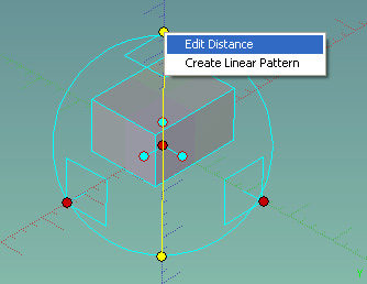
When you select Edit Distance, you will get a dialog box that
lets you enter a number for distance.

What distance is this? This is the distance you want to move the origin of the
triball along the axis of the selected handle. If you press OK in
the dialog box above, the block will move up three units in the z
direction. Try some different values. Remember the Fit to Screen
button will get your part back in view.

1.3 Relative positions and orientations
Drag a cylinder into your scene. Be sure it is separate from the
block. That is, be sure that none of the points on the block is
highlighted when you drop the cylinder into the scene. Notice that
as you drag your cursor over the screen, that IronCAD displays the
coordinates for the anchor of the cylinder.

Notice the thin green lines in the screen dump above. As you move
the mouse around, you should see the coordinates change. If I drop
the cylinder there, it will be on the x-z plane, not the x-y plane:

If you selected a scene with the x-y-z plane datum, as
you drag your part around the scene, you can tell which
plane your part will drop on depending on which plane is
currently highlighted in green. Drop the cylinder
somewhere on the
x-y plane apart from the block.

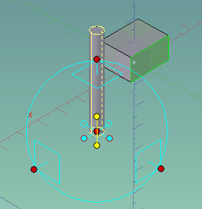
Now, resize the cylinder using the IntelliShape handles to make
it tall and thin.
Reminder: To get the IntelliShape handles, click twice on a part (or
click until the part turns yellow).

With the cylinder selected, click on the triball icon. (Or press
F10, or select Tools -> Triball). The triball should appear
on the cylinder centered at its anchor point.

Notice that the triball also has interior handles. Right click on the vertical
interior handle. You will get a menu that lets you position the current part
relative to another part, surface, point or axis. Select Perpendicular to
Face.

After you select this, move the cursor around. As you move the
cursor close to a face in they scene, it will turn green indicating
that it is the current face. In the scene below, the face closest
to the cylinder is currently selected.
If you click on this face, the cylinder will rotate so the selected
axis is perpendicular to the selected face. (Note that if you click
on the top face, nothing will happen since the cylinder is already
perpendicular to the top face.)

Try selecting different faces and different options. Use the undo
button between selections so that you maintain your orientation.
Next, we are going to move the cylinder to the block. Without
selecting an axis, right click on the center point of the cylinder�s
triball. You will get the following menu:
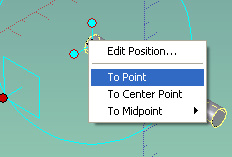
Select the To Point option. As you move the cursor around,
points on the block will be highlighted. In the screen dump below,
I moved the anchor of the cylinder to the center of one of the faces
of the block.

Note: The orientation of the cylinder doesn't change. So if you
have rotated the cylinder to an angle, it will move the
center point to the point on the block that you select,
but it won't align the faces.
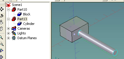
Note: You have only moved the cylinder. You have not joined the cylinder
and the block together. To see this, click on the scene browser.

Look at the two parts. (Your part numbers will probably be different from
mine.) The block and the cylinder are separate.
Aside: If you want to join them into a single part, you can select Shape->
Boolean to perform the Boolean union operation.
Click to undo the move action. Making sure the cylinder still
has the triball active, right click again, but this time, select
Edit Position:
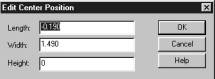
This dialog box allows you to specify the exact location of the anchor point
of the object. I changed all the values to zero. When I pressed OK, the cylinder
moved to the origin. Try moving the cylinder around using the edit position
dialog box.
With the triball still highlighted, right click away from any of the handles.
This gives you general options for controlling the triball and moving the part.

For example, the default is to move the triball and the shape together. Click
on the second option (Move shape only). Now when you move the cursor,
the triball stays in its original location and the part moves.
Try the third option. (Position triball only). With this option selected,
the triball should turn white, indicating that it is the active object. As
you move the cursor, the triball will move and the part will stay in place.
Note: You can also select the triball, by pressing the space bar. In
the beginning, you are more likely to do this by mistake rather than on purpose.
If the triball isn�t doing what you expect, look at its color. If it�s white,
press the space bar and it will return to its normal behavior.
Undo the moves and re-select Move Shape and Anchor, which is the behavior
that you normally want.
1.4 Copying and moving
Click undo several times until the cylinder is upright again. In the scene browser, select Cylinder. The cylinder in the drawing
area will be selected. Click on the Triball tool. Right click on the
center of the triball and start to drag the mouse. When you release
the mouse, you will get a pop-up menu that lets you move, copy or link
the object.
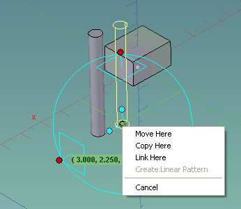
Select Copy Here. You will get the following dialog box:

Changed the Number to 2 and Distance
to 2.5. When you click OK, you will have 2 copies, spaced 2.5 inches
apart in the direction you were dragging.
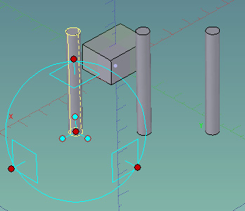
Select the first cylinder again. (Check in the scene browser to
be sure you have just the cylinder, not the whole part selected.)

Right click on the center of the triball and drag in a different
direction. This time select Link Here. You will get the same
dialog box. Enter the same values.
You should have two more copies of the cylinder

Hit escape or toggle the triball tool button to remove the triball
from the first cylinder. Click on the cylinder until you have the intellishape
handles. Now pull on one of the handles to resize this cylinder.
The cylinders that are linked copies change when the original cylinder
changes. The simple copies do not. Notice that the scene
browser indicates which copies are linked copies by using
the shortcut icon on the linked copies.

Try changing one of the linked copies. All the linked copies changed.
This makes sense when you are working on a part because you cannot
always remember which was the original shape. Notice that the scene
browser indicates which copies are linked copies by using
the shortcut icon on the linked copies.
2. Short review from the previous lab
With the block selected, select View -> Sizebox dimensions
Nothing will happen right away. This is a toggle switch for viewing options.
Click twice on the block and you will see the dimensions.
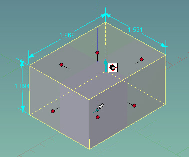
Select one of the handles, and right click on the handle. Select
Edit Sizebox. You will get a dialog box that allows you to
change the length, width and height of the box. How do you know
which way the dimension will change? It will change the dimension
in the direction of the handle that you selected. Change the length
and press OK. IronCAD changes the length of the box by moving the
left-hand face.
To change the resizing behavior, right click on a face of the block and select Intellishape Properties.

You will get a dialog box with many tabs. Select the Sizebox
tab. Notice that you can change the length, width and height of the
part in this menu as well as change the default behavior of the resizing
operation. Pull down the menu next to Length and select About
anchor.

Click OK. Grab the left-hand handle again. As you move the handle, you will
see that IronCAD now resizes the length around the anchor rather than from the
opposite face. Since we didn�t change the resizing behavior for the width or
height, they will still scale from the opposite side. After you understand
how this works, go back to the Sizebox menu. (Right click on a face
and select IntelliShape Properties.) Make the default behavior to resize from
the opposite handle.
Look at the Interaction tab. This tab allows you to control how shapes
are combined when you use drag and drop editing.
3. Putting the small holes in the fan plate
The part we are making is the fan blade housing from Lesson 3 in the IronCAD
tutorial.

While you are looking at the drawing, notice that the centers of the small
holes are 0.295 inches from the edge.
Open fanhousing.ics from your desktop. This file has
everything except the holes in the corners and the beveled edges. Zoom
in on one of the corners by selecting the magnifying glass with the
window.

Drag an H-cylinder (negative cylinder) onto the top face of the
corner. Be sure that the top face is highlighted. You
may get the following dialog box:
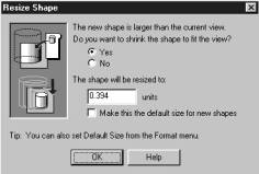
Say OK. This will make the cylinder about the right size for the current view.
Use the IntelliShape handles to make the cylinder go all the way through both
plates.
To size the hole, right click on the top handle. Select Edit Sizebox.
The radius of the hole is 0.089 inches, so the width is 0.089*2. Remember that
for cylinders, you only need to specify either the length or the width since
they have the same value. The height of the negative cylinder doesn�t matter
as long as it extends beyond both plates.

3.1 Locating the hole
Now that the hole is the right size, we will get it in the right
location -- with its center 0.295 inches from each edge. With the
hole selected, click on the triball tool button.

Strategy: We are going to move the center of the hole to the corner
of the plate. This is easy using smart snap. (Reminder: We used smart
snap to get remove the extra pieces of the cylinder in the last lab.) Then
we will use the triball to move the center of the cylinder to exactly 0.295
inches from the edge.
Select (normal left click) the center of the triball. With the shift key depressed, move
the cursor until the center point of the arc for the blend is highlighted.
Release the mouse. You will see a small cylinder removed from the top and
bottom corners.

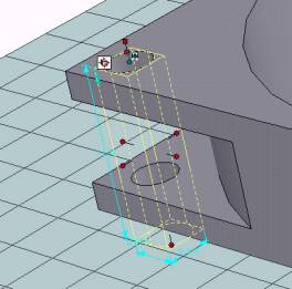
Right click on the triball axis parallel to the x-y plane. It will
turn yellow, indicating that it is locked, that is, that the cylinder
can only move along this axis.

Grab one of the highlighted handles and move it to the right. You
will see a dimension showing you how far you have moved the part. We
want to move it 0.295 inches from the edge.

Rather than trying to position it with the mouse, release the mouse
and right click on the dimension. Select Edit Value.

You will get a dialog box. Enter 0.295:

The hole will be positioned on the edge of the plate, 0.295 inches
from the corner. Select and lock the other axis. Using the same
technique, move the hole to 0.295 inches from the corner.

3.2 Copying the hole
Now we are going to use the triball to copy the hole to the other
corners. If one axis of the triball is still yellow (locked), click
somewhere in the background to unlock it.
Strategy: We are going to move the triball to the center of the
fan housing. We will then make 3 linked copies of the hole, each at
90 degrees from the original. The holes should be linked because if
the diameter of one hole changes, they should all change. Zoom out to
see the entire part.
Press the space bar once. The
triball should turn white. This allows us to move the triball without
moving the part. Right click on the center of the triball and select
To Center Point.

Move the cursor toward the center of the part. When the top circle is highlighted
(green), drop the triball. Notice that the hole is still selected, but its
triball is now centered on the entire part, not on the hole.

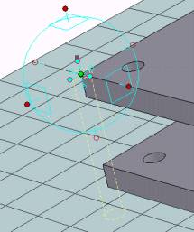
Press the space bar so that the triball and the part work
together. The triball should turn cyan (blue). In the earlier example,
our copies were a fixed distance from the original. This time, we want
to move the copies through an angle -- that is, we want to rotate
rather than translate. We want to rotate about the z axis, so lock
the z axis by clicking on its handle. Your scene should look
something like:

Right click within the triball -- but not on any handles or objects.
As you move the cursor, the hole will rotate. Release the mouse anywhere.
You will get the pop-up menu. Select Link Here.
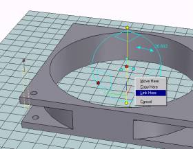
Because you were rotating when the link option was selected, this time you
will be able to enter an angle rather than a distance. You want 3 copies at
90 degrees.

When you press OK, you will have four holes in the corners of the part!

3.3. Blending
To end this lab, we will bevel the corners of the part. (If you look back
at the drawing, you will see that the outer corners of the part are rounded.) Select
the tool button for Blended Edges.

A new toolbar will appear. This toolbar lets you select whether you want to
bevel a vertex, an edge or a face. The options in the toolbar also let you
enter the type of blend and the radius of the blend. You can also select a
variable blend and specify the start and end blend radius.
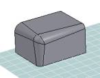
To see how these options work, lets start with a practice part. Drag
a block into your drawing area, away from the fan housing. In the
first option, select Face/Edge/Vertex. In the second option,
select constant, and in the third option, select
0.158. (These are probably the defaults.)

Move your mouse around the block. Your cursor should change shape. The cursor
will look like a dot when you are close to a vertex, the point at which
several lines and faces meet. The cursor will look like a line when you are
close to an edge, the line where two faces meet, and it will look like
a sheet of paper when you are over a face, one of the surfaces of the
part. (Again, since the cursor doesn't show up in the screen dumps, I can't
show you this.)
First, select a vertex. Notice that IronCAD shows you where the blends will
be applied.
 
If you want IronCAD to make the indicated blends, press the green go
button. If you don't want IronCAD to make the blend, press the red X
button.

After you make this blend, press the undo button, and then try the other options
to see how blend works when you select edges and faces. Notice that the blend
toolbar disappears after the blend is created. You need to select the blend
tool again to get it back.
Finally, change the type of blend from Constant to Variable.
You will now be able to enter a start and end radius for the blend. Press the
go button again. Here is a variable blend on a vertex:
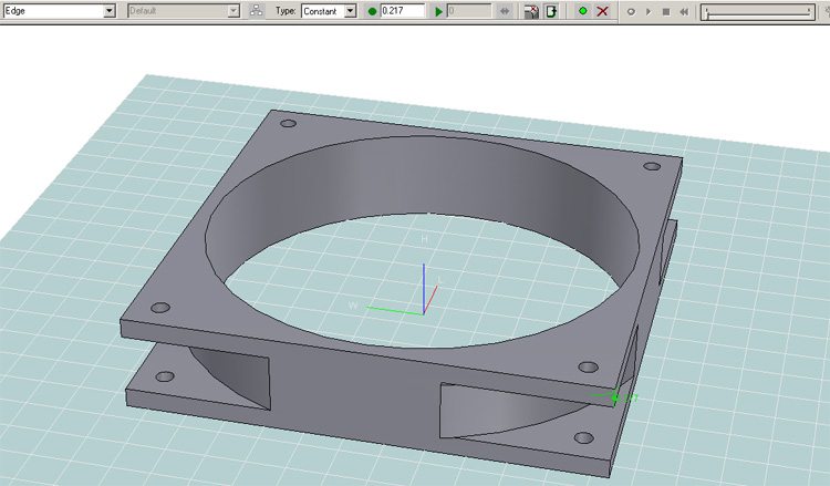
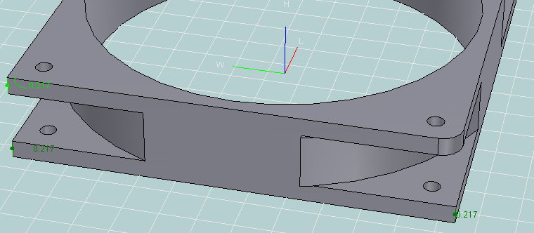
Now we are ready to blend the corners of the fan housing. Press the blend
tool button. From the drawing, we know that the blend radius of the corners
is 0.217. Enter this value for the blend radius and check to be sure that the
blend radius is constant.
From the pull down menu on the left part of the blend tools, select
Edge. This will ensure that only edges (not faces or vertices)
will be selected -- although you still have to be sure that you pick
the right edge.
With the blend tool on and the blend radius set to 0.217, select one
of the edges (lines) at the corner of the part.
Press the Go button. IronCAD will blend the edge.
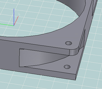
Turn on the scene browser, if you don't already have it turned on.
The blend will appear as an object in your part.
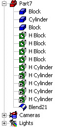
Work your way around the part applying the blend to each of the eight
corners. You can do multiple selects before pressing the Go
button.
Selecting several corners to blend at the same time saves time -- but
it is difficult to deselect a single blend if you make a mistake. If
you make a mistake, you can use Edit -> Deselect All, press the
Cancel button, or press Go, and then delete the
incorrect blend using the scene browser.

Once you have blended all eight edges, the part is done!


sfinger@ri.cmu.edu
| 
