Using a laser pointer and a matrix LED as a two-dimensional input device


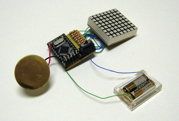
Laser Command is a game which I build using a 8x8 matrix LED and an Arduino Mini. This game was developed as a "sample" class project in S10-05833 Gadgets, Sensors and Activity Recognition in HCI. The class is taught by Scott Hudson at Carnegie Mellon University, and I'm doing TA for the class. The name "Laser Command" comes from an old game called Missile Command. In Missile Command, you are asked to shoot enemy's missiles using missiles. In Laser Command, you shoot using laser, i.e., a laser pointer.
The most interesting part in this game is that the game uses a laser pointer as a two-dimensional input device in conjunction with a matrix LED. Here are a video, explanations of how it works, circuit diagrams and source code. I hope that these are enough for you to replicate and/or build on the technique :)
How it works
Essentially, I make a 8x8 matrix LED as a 8x8 light sensor array using two techniques.
In the followings, I will explain how the two techniques work using a simplified example shown below.
The example consists of two digital ports (D0 and D1), two analog ports (A0 and A1) and four LEDs,
i.e., a 2x2 matrix LED.

Reverse Bias
The first technique is well-known technique for using LEDs as light sensors. In this technique, we charge LEDs by applying reverse bias, and, then, measure how quickly the charged current leaks after stopping the reverse bias. In the example here, the technique works as follows:- Reverse bias the LEDs by making D0 and D1 HIGH, and A0 and A1 LOW.
- Make D0 and D1 INPUT. Initially, both of them are HIGH because of current charged in the LEDs.
- Then, as the current leaks, D0 and D1 becomes LOW after a certain period.

This technique is sufficient if we just want to use a single LED as a light sensor.
But, it is not sufficient if we want to use a matrix LED as a light sensor array.
As described above, we can detect which row is pointed by a laser pointer,
but we cannot distinguish which column is pointed because LEDs at the same row share a cathode.
So, we need one more technique to detect which column is pointed.
Direct Measurement
The second technique is not commonly used because it requires analog inputs. When we project strong light on LEDs, the LEDs are charged. In this technique, we directly measure the voltage generated by the charged LEDs as follows:- Discharge all current stored in the LED by making all ports LOW.
- Then, measure voltage at A0 and A1 using analogRead(). The voltage is proportional to the brightness.

Circuit
Here is a circuit diagram which you can use with sensor sample source code. The circuit is a 8x8 matrix LED version of the example (2x2 version) discussed above. In the circuit, A6 and A7 are connected to D11 and D12 receptively. This is because these two ports do not work as digital outputs. This circuit requires eight analog inputs, so that you need an Arduino Mini, Nano or Mega (or whatever which supports more than eight analog ports). If you use an Arduino Duemilanove, you still can make a 8x5 matrix LED as a light sensor array with slight modifications.In Laser Command, I also connected D10 to a piezo in addition to this circuit diagram.

Source Code
Here is a sample code which make a 8x8 LED matrix a light sensor array.Download a sample code
Also, here is a source code of Laser Command.
Download Laser Command
//
// Using a Laser Pointer and a 8x8 Matrix LED
// as Two-dimensional Input device
//   Developed Eiji Hayashi
//   2010/03/26 Version 1.0
//
// *** What's this? ***
// This is a sample code which shows how we can use
// a 8x8 matrix LED as a light sensor array, and
// how we can detect position of a LED pointed by
// a laser pointer.
//
// *** Wiring ***
// This code assumes:
//   D2 to D9 are connected to cathodes
//   A0 to A7 are connected to anodes
//   D11 and D12 are connected to A6 and A7 respectively
// Please refer to circuit diagrams for more details.
//
// *** How it works ***
// When you turn on a circuit, all LEDs turn on one-by-one.
// After that LEDs pointed by a laser pointer turn on.
//

#include <avr/delay.h>

// A technique to make analogRead faster
// See http://www.arduino.cc/cgi-bin/yabb2/YaBB.pl?num=1208715493/11
#ifndef cbi
#define cbi(sfr, bit) (_SFR_BYTE(sfr) &= ~_BV(bit))
#endif
#ifndef sbi
#define sbi(sfr, bit) (_SFR_BYTE(sfr) |= _BV(bit))
#endif

int screen[8] = {0,0,0,0,0,0,0,0};  // bits displayed on the LED matrix
int thresh[8] = {0,0,0,0,0,0,0,0};  // threshold values used in CheckColumn()
                                    // the thresholds are adjusted in
                                    // adjustThreshCol()
// Initial setup
void setup(){
  int rows[8] = { 2, 3, 4, 5, 6, 7, 8, 9};
  int cols[8] = { 14, 15, 16, 17, 18, 19, 11, 12 };

  //Serial.begin(9600);
  DDRC = B11111111;
  DDRD = B11111111;
  PORTD = B11111111;

  // Adjust prescaler to make analogRead faster
  sbi(ADCSRA,ADPS2) ;
  cbi(ADCSRA,ADPS1) ;
  cbi(ADCSRA,ADPS0) ;

  // Adjust threshold for column detection
  adjustThreshCol();

  // Turn on LEDs one-by-one for sanity check
  for( int i=0; i<8; i++ ){
    pinMode( rows[i], INPUT );
    pinMode( cols[i], OUTPUT );
  }

  for( int i=0; i<8; i++ ){
    pinMode(rows[i], OUTPUT );
    digitalWrite( rows[i], LOW );
    for( int j=0; j<8; j++ ){
      digitalWrite( cols[j], HIGH );
      delay(50);
      digitalWrite( cols[j], LOW );
    }
    pinMode( rows[i], INPUT );
  }
}

// Main loop
// Detect a laser pointer and turn a pointed LED on
void loop()
{
  // detect a pointer
  // if no pointer is detected, 8 will be returned.
  int row = checkRow();
  int col = checkColumn();

  // put 1 at the pointed location
  if( row != 8 && col != 8 )
     screen[row] |= 1 << col;

   /*
  Serial.print(row);
  Serial.print(",");
  Serial.println(col);
  */

  // Show the content of screen
  DDRC |= B00111111;  // make column 0 to 5 port output
  DDRB |= B00011000;   // make column 6 and 7 output
  DDRD &= B00000011;  // make row 0 to 5 input
  DDRB &= B11111100;  // make row 6 and 7 input

  for( int i=0; i<5; i++ ){
    for( int row=0; row<8; row++ ){

      if( row<6 ){
        DDRD |= 1 << (row+2);
      }
      else{
        DDRB |= 1 << (row-6);
      }

      PORTC = screen[row] & B00111111;
      PORTB = ( screen[row] & B11000000 ) >> 3;
      _delay_us( 300 );

      DDRD &= B00000011;
      DDRB &= B11111100;
    }
  }
}

// Check which column is pointed
int checkColumn(){
  int val[8];  // brightness

  // *** clear charges ***
  // make all anodes output and low
  DDRB = B00011000;
  PORTB = B00000000;
  DDRC = B11111111;
  PORTC = B00000000;

  // make all cathodes output and low;
  DDRD |= B11111100;
  DDRB |= B00000011;
  PORTD &= B00000011;
  PORTB &= B11111100;

  _delay_us(10);  // wait for a while to clear charges

  // make all anodes input to measure charges cause by light
  DDRB &= B11100111;
  DDRC = B00000000;

  _delay_us(200);  // wait for a while

  // read analog values at all anodes
  for( int col=0; col<8; col++ ){
    val[col] = analogRead( col );
  }

  // calculate difference between current values and thresholds
  for( int col=0; col<8; col++ ){
    val[col] = val[col] - thresh[col];
  }


  // if the differences are bigger than 10,
  // the column is pointed by a laser pointer
  int signal = 8;
  for( int col=0; col<8; col++ ){
    if( val[col] > 10 ){
      signal = col;
      break;
    }
  }

  // uncomment the following to see sensor values via serial communication
  /* for( int col=0; col<7; col ++ ){
    Serial.print(val[col]);
    Serial.print(",");
  }
  Serial.println(val[7]);
  */

  return( signal );

}

// Measure analog values at anodes to calculate threshold values.
// Using the threshold values mitigates effects of ambient light conditions
void adjustThreshCol()
{
  for( int cnt=0; cnt<100; cnt ++ ){  // measure the values 100 times and take average
    int val[8];

    // *** clear charges ***
    // make all anodes output and low
    DDRB = B00011000;
    PORTB = B00000000;
    DDRC = B11111111;
    PORTC = B00000000;

    // make all cathodes output and low;
    DDRD |= B11111100;
    DDRB |= B00000011;
    PORTD &= B00000011;
    PORTB &= B11111100;

    _delay_us(10);  // wait for a while to clear charges

    // make all anodes input to measure charges cause by light
    DDRB &= B11100111;
    DDRC = B00000000;

    _delay_us(200);
    int input = 0;
    for( int i=0; i<8; i++ ){
      val[i] = analogRead( i );
      thresh[i] += val[i];
    }
  }

  // take average
  for( int i=0; i<8; i++ ){
    thresh[i] = thresh[i] / 100;
  }
}

// Check which row is pointed
int checkRow()
{
  int input = 0;

  // *** Apply reverse voltage, charge up the pin and led capacitance
  // make all cathodes high
  DDRD |= B11111100;
  DDRB |= B00000011;
  PORTD |= B11111100;
  PORTB |= B00000011;


  // set all anodes low
  DDRC = B00111111;
  PORTC = B11000000;
  DDRB |= B00011000;
  PORTB &= B11100111;

  _delay_us(100);  // wait for a while to charge

  // Isolate the pin connected to cathods
  DDRD &= B00000011;  // make N0-N5 INPUT
  DDRB &= B11111100;  // make N6 and N7 INPUT

  // turn off internal pull-up resistor
  PORTD &= B00000011; // make N0-N5 LOW
  PORTB &= B11111100; // make N6 and N7 LOW

  // measure how long it takes for cathodes to become low
  int val[8] = {100,100,100,100,100,100,100,100};
  for( int cnt=0; cnt<50; cnt++ ){  //you may need to adjust this threshold
    for( int r=0; r<8; r++ ){
      if( digitalRead( 2+r ) == LOW && val[r] == 100 )
        val[r] = cnt;
    }
  }

  // uncomment the following if you want to check values
  /*
  for( int r=0; r<7; r++ ){
    Serial.print( val[r] );
    Serial.print(",");
  }
  Serial.println( val[7] );
*/
  // if a pin becomes low quicker than 50, the pin is pointed
  int signal = 8;
  for( int i=0; i<8; i++ ){
    if( val[i] < 49 ){
      signal = i;
      break;
    }
  }

  return( signal );
}

© 2010 Eiji Hayashi. Some rights reserved.