Obtain a set of required parts.
Glue a white servo connector horn to each of the three
omni-wheels hubs using a cyanoacrylate "super" glue or similar
adhesive. Make sure the servo horn is well centered on the wheel hub.

Connect each omni-wheel to a servo. Using a narrow Phillips
screwdriver that fits inside the omni-wheel hub, tighten the screw that
holds the plastic servo horn to the servo shaft.


Apply a rectangle of double-sided foam tape to the top of
each of the three servos. This will attach each to the base plate; be sure
to observe the orientation as illustrated.

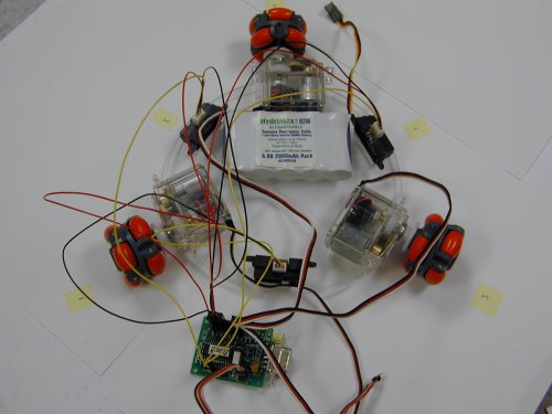
Attach the servomotors to the base using the double-sided
sticky tape, placed at 120 degree angles with respect to each other. The
axis of each motor and wheel should be aligned with the center of the disc,
the three axes equally spaced around the perimeter, and each motor aligned
with the edge of round base plate.

Use double-sided foam tape attach the battery to the base.
Note: if you have a battery that is too big or just does not fit under the
robot, you can instead attach it on the top of the robot.

Attach the IR sensors to the base using foam tape, located
between adjacent servos. Place them approximately 1/2...1" from the
edge of the disc in front of them.

Connect the wires from the servomotors, sensors, and battery
to the Pontech Serial Servo Controller board (SV203) as described in the
following diagrams. It may also be helpful to refer to the diagrams found in
the SSC and IR handbooks. Number the servos clockwise (it is helpful to
label them with pen or tape) and connect the wires to the SV203 board in the
same order. Number all the IR sensors such that the number of the sensor is
the same as the number of the opposite servo (across the base). All servos
must have the Futaba style connectors: ground (black or brown), power (red),
input signal (white or orange).


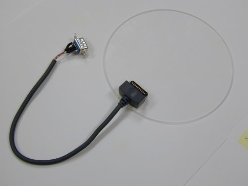
In the next several steps the Palm is connected to the SV203
using the Palm's HotSync connector, the HotSync Cable, and the DB9 connector
on the SV203. For the first step, cut the Palm's HotSync cable approximately
8 inches from the connector that attaches to the Palm itself. Solder the
exposed HotSync cable wires to a male DB9 connector as follows, using short
lengths of heatshrink tubing to insulate the pins as illustrated:
Red wire - pin 5
Black wire - pin 3
Brown wire - pin 2


Mount the Palm Pilot on top of the robot by plugging it into the HotSync Cable's connector. The connector will securily hold Palm Pilot in place.