


Don't panic! This requires no prior knowledge of electricity or other physics!!
Why? Because computers are fundamentally information processing devices, rather than electrical devices.
The first computer was designed by Charles Babbage in the 1800s,
made out of a barn full of gears! It would've worked, but they
couldn't make gears precisely enough at the time.
The first programmer was Lady Lovelace ("Ada"). She wrote
programs for the un-built Babbage "engine", and came up with a lot of modern
CS ideas.
All of this work was rediscovered after it had been re-invented.
The basic question: How do we get a bunch of switches to
First question: how do we get switches to calculate things?
Remember Java's boolean operators? Like && and ||?
With values of true/false?
Well, boolean mathematics (with true represented as 1) is
heavily used in the design of basic logical circuitry (which is the
basis for nearly all computer circuitry).
First, let's look at the truth table for the logical (boolean) AND operation:
| A | B | A and B | 0 | 0 | 0 | 1 | 0 | 0 | 0 | 1 | 0 | 1 | 1 | 1 |
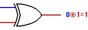
The other main logical operation is OR:
| A | B | A or B | 0 | 0 | 0 | 1 | 0 | 1 | 0 | 1 | 1 | 1 | 1 | 1 |
You can build logic gates for both of these operations out of simple combinations of switches:
         A      B
        _|_    _|_
    *__|   |__|   |__out == A and B
|
 |
            A
           _|_
        __|   |__
    *__|    B    |__out == A or B
       |   _|_   |
       |__|   |__|
|
 |
Connecting a switch ``backwards'' gives us the NOT operation:

(The "+" and dot in the diagrams are boolean math symbols for OR and AND.)
(Most of these lovely diagrams are borrowed from
http://www.play-hookey.com/digital/.)
We can also combine these basic elements to make other useful logic gates:
| NAND (not and) |

|
| NOR (not or) |

|
| XOR (exclusive or) |
|
So, how do we make an XOR circuit? We can design it using truth tables (or boolean mathematics).
Here's the truth table that we want for XOR:
| A | B | A xor B | 0 | 0 | 0 | 1 | 0 | 1 | 0 | 1 | 1 | 1 | 1 | 0 |

Amazing fact: you can actually build this (or any logic circuit)
entirely out of NAND gates:

So, what are the rules of binary addition?
1102 plus 112 == 10012
It turns out that you
can write a truth table for the binary addition of one digit.
The rules are analogous to the rules you use when adding in base 10, but
much simpler:
| A | B | A plus B | Carry | 0 | 0 | 0 | 0 | 1 | 0 | 1 | 0 | 0 | 1 | 1 | 0 | 1 | 1 | 0 | 1 |
So we know how to build a 1-bit (half) adder from gates:

We call it a half adder because we left out one complication: if
it's not the lowest digit, there might be a carry in:

By adding in the carry-in, we get a real 1-bit full adder! To
simplify things, we can refer to this whole circuit as one box:

(Note: we've added another layer of abstraction!)
By plugging N of these together, we get an N bit
integer adder.
Here's a 4 bit adder:

The number of these that you need (N) depends on how many bytes your
integers are.
Well, one basic design for a 1-bit memory is an R-S flipflop
("R-S" stands for "Reset-Set"). This depends on feedback to stay in
whichever state it was last put into:

So in this design each bit of RAM uses at least four switches.
We're actually pretty close.
Suppose we have a set of arithmetic function boxes, like
the adder we saw above. (And also some condition testing/remembering boxes.)
And some control logic to route
information to one box or another, and route the output from the selected box.
We could then have a set of bits that we store in a set of flipflops (called an instruction register) that determine which function boxes are used at the moment. And a program counter that holds the address of the next instruction to be used. Some instructions might cause the selection of the next instruction to depend on the current status of the condition tests, by changing the PC. And there could be a clock to cause the computer to go from one instruction to the next.
If the instructions are stored in the same memory as the data they
will operate on, we have described a
von Neumann architecture computer, the basic design used in
the Central Processing Unit (CPU) of essentially all commercial computers:
