Vehicle Propulsion Dynamics
By: Jonathan Bates, Alex Hanson, and Aanchal Raj

Objectives
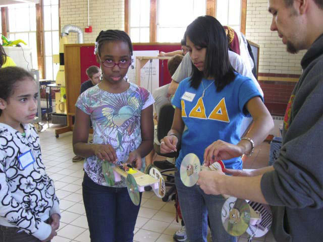
Use a simple mousetrap powered vehicle to reinforce basic propulsion, energyconservation, and mechanical advantage concepts. The modular car design consisting of multiple gears mounted to the rear axle and variable length lever arms allow for rapid change in configuration. Visitors modify the mouse trap powered vehicle to achieve distance and power objectives. The concepts behind engineering design are further developed via this optimization process.


Preliminary Testing
Prototypes
Initial Prototype Design:
- Only consisted of varying lever arms
- CDs were used as temporary wheels and pink foam was used as temporary axle mounts.
- Tape was used to affix the string between the back axle and lever arms
- Two lever arms of varying length were attached to the same car
- Hot glue was used to mount the wheels

Second Prototype:
- The CD's and foam were discarded from the design.
- The foam was replaced with wood planks with ball bearings mounted in them.
- The gears were placed on the rear axle
- String attached to the gears via a loop and hook system.
- Only one length of lever arm was attached to the car.


Final Design:
- The final design was basically the Second Prototype, but with a more sophisticated gearing system.
- The string on the second design would slip off the gear and the car would not move.
- A track sytem was developed to combat thisdesign flaw, where a smaller circle was placed between two of the originall gears producing a track to guide the string.
Production of the Final Design:
- A laser cutter was used in production of the gears and wheels, substantially narrowing tolerances. The gears consist of circles (of varying diameter) with a small hook cut out of them for attaching the string.
- Bearings: Flanged bearings were utilized to provide more stable mounting. We chose steel, sealed bearings (ABEC-5).
- Axles and levers consist of hollow aluminum tubing.
- The body of the of the cars are made out of plywood and cedar stock. The band saw, drill press, and reamer were used in the production of these pieces.
- Due to material and fitment limitations, glue was used to permanently bond wooden pieces.
What We Learned:
- Practical application of both automated and human controlled rapid prototyping equipment
- Application of Computer Aided Design (CAD)
- Complete prototyping lifecycle
- Presenting and communicating engineering process to varying age demographics
Poster - CAD Files - Student Worksheet - Teachers Instructions