
This is the original sketch from which the magnetic maze toy was derived. The user is able to nagivate through the maze by rotating the maze in all three axes.
Toy Manufacturing Report
Concept
Horizontal mazes that you tilt left and right, up and down to get the ball around trap holes to the end are quite common. Vertical mazes, though, are a unique sight. A new spin on an old game is the Magnetic Maze. The child holds the maze vertically and uses a magnetic wand to guide the metal ball through a series of paths to the exit of the maze. The child may make the maze more challenging by adding more balls or by covering parts of the maze so that he or she must complete that part of the maze by touch or by memory. The simple yet entertaining design is a safe, compact toy for children four or older.
This is the original sketch from which the magnetic maze toy was derived. The user is able to nagivate through the maze by rotating the maze in all three axes.
Manufacturing Process
We decided to make our maze out of machinable plastic, as it is cheap and easy to work with. We were originally going to mill out the path of the maze but the precision required and the unforgiving consequences of a mis-cut were too great for human hands. We decided to model our product with computer aided drafting (CAD) software, and then run it through a computer numerical controlled (CNC) machine.
Our first CAD model was drafted in SolidWorks and each maze section, such as a hallway or corner, was drafted as a part. The final SolidWorks model was an assembly of the smaller maze parts. Unfortunately, because the maze was drafted as many parts put into one assembly, it could not be successfully exported to the CNC machine, as the machine needed a single line to follow and our model had many boundary lines.

The assembly of the maze can be seen here with all the boundary lines. These conflict with the intended path of the CNC machine and a new CAD model had to be drafted as one solid piece.
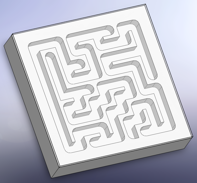
The final CAD model was drafted in SolidWorks by extruding a block and extrude cutting the path of the maze. This was able to be exported to the CNC machine via Mastercam.
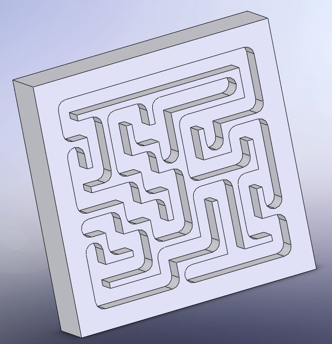
This is the final version of the CAD model. This was exported to Mastercam, which computes and exports the cutting path for the CNC machine.
A block of machinable plastic was squared by hand in a milling machine to prepare it for its run through the CNC machine. This block had to be larger than the final dimensions, as it needed to be clamped in the CNC machine.
The results from the CNC machine were perfect, as the cuts were precise and smooth and there was no additional work required on the block. After the maze portion was completed, a cover for the maze and a magnetic “pen” still needed to be completed.
The cover of the maze is 1/8” Plexiglas. Cutting Plexiglas square is a difficult task with a band saw, as one is required to set up jigs. Instead, a laser cutter was used to cut the sheet. To make a cut, the laser requires the desired shape drawn in .dwg or .ai file with lines colored in pure red or RGB triplet (255, 0, 0; 8-bit). After the cover was cut, it was glued onto the CNC machined block with an epoxy that has a good bonding affinity with plastics.
The magnetic pen was a magnet placed inside a bored hole of a wood dowel. Decorations were made with a band saw. A 3/8” steel ball bearing was used to use in the maze.
This is the final assembly of our maze. The ball and start/finish holes are not included in this model.
Design and Manufacturing Issues and Afterthoughts
Our maze was originally 9 by 9 inches. However, due to the size constraints and limitations of the CNC machine, we had to scale our project down by a factor of two. The hole in the wood dowel pen was bored with a regular drill bit and a spade bit would probably have made the job easier. Otherwise, project conception, design, and construction went rather smoothly.
Kay Csuri
Paul Kim
Ryan Yates
Carnegie Mellon University
Rapid Prototyping Design (39-245)
Section A
Spring 2008