You can find the source code here,
and it's zipped up with the necessary make files here.
(The links to the source codes are temporarily disconnected from this page.)

 (click an image for full size view)
 Starting Configuration   			Random Samples       Roadmap Construction #1


Resampling   			     Reconnect + A*  				Improved Path


Another Environment


PRM This implementation is for a 5 link moving robot in a 2D workspace. The planner creates a probabalistic roadmap with 2 sampling steps and 2 connection steps. Finally the path is found and smoothed. The details of this implementation are described below.
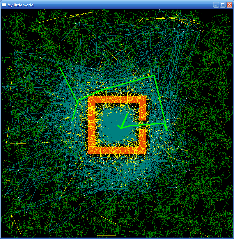
Initial Sampling The initial sampling is done with random X,Y coordinates and random joint angles. Before a sample is placed, it is checked for collision with an obstacle. If it intersects an obstacle, a random direction is picked, and the robot is moved and checked until it no longer intersects an obstacle. The initial randomly sampled configurations of the robots are seen as green squiggles in the images above.
Nearest Neighbors To connect the nodes to their neighbors, the nearest neighbors must be found. A distance metric based on the euclidean distance of the bases and a 'distance' between the Nodes' joint angles. In this distance metric the proximal joint angle differences are weighted more than the distal joint angles. The distance metric has 'weights' associated with the translational and rotational distances, and can be tuned for straighter paths, or less wiggling. Each node is checked against all other nodes and the top 5 nearest neighbors are tested for connection.
Connection Testing To test for connection, a series of temporary nodes are created between the two test nodes. Each is checked for intersection with an obstacle by testing each link for intersection with each obstacle edge. They nodes are created and checked sequentially, and while this is not the most efficient, it can be directly re-used to animate the graphics during local planning between the final path points. If two nodes are found to have no intersecting temporary nodes between them they are labeled as connected. Otherwise their 'failed connections' number is incremented. Failed connections are seen as yellow lines in the images and movies.
Re-Sampling Since the first sampling is not sufficient to create a roadmap for most environments, a re-sampling is done with points focused near the edges of obstacles. For each node, new nodes (proportional to the number of failed connections) are created with a gaussian distribution of coordinates and joint angles with a mean of the parent node. Since there are more failed connections near obstacles, most of the new samples (seen as white dots in the images) appear near obstacles. Again, intersecting configurations are moved into safe areas in a random direction.
Re-connection The same connection algorithm as before is run on all of the nodes, and the connections are updated.
Roadmap Search Using the now partially connected roadmap, an A* search is done to find an 'optimal' path from the starting configuration to the goal. Unfortunately, since nodes are only connected to their local neighbors, this path is often quite circuitous. This path is shown as a bright green line in the images.
Path Refinement One fairly easy way to improve the path is to try to connect all of the Nodes which make up the A* solution to each other, and then to throw out the path and run A* again. This generally results in a much smoother and simpler path, particularly in open areas. This line is bright pink in the images.
Finally the robot is animated along the final path to the goal. Movie file #1
Mike Murphy 2006