Exploring Tekkotsu Programming on Mobile Robots:

Forward Kinematics

Prev: Vectors
Up: Contents
Next: Inverse kinematics

Contents: Introduction, Kinematic chains, Reference frames, Converting between reference frames, Interest points, Body and leg descriptions, Stare at paw demo, Ground plane calculations

Introduction

Kinematics is the study of how things move. In particular, we want to have methods for precisely calculating the position of points on a manipulator (forward kinematics). Further, we need to know which joint values will achieve a desired position (inverse kinematics) in order to produce controlled motions.

Manipulators are constructed from a series of links, each connected by an actuator. A series of links is also called a chain, with one end defined as the base, and the other called the end effector. Actuators are commonly either revolute joints which cause rotation about an axis, or prismatic joints, which cause translation along an axis. All of the AIBO's and Chiara's joints are revolute, but some types of robot arms include prismatic joints..

The AIBO's Kinematic Chains

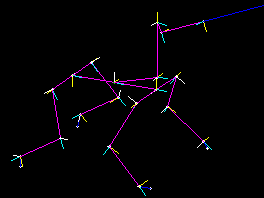
Tekkotsu includes a kinematics engine for calculating the positions of points on the robot's body from joint angles (forward kinematics), or the joint angles necessary to give a point on the robot a particular position and orientation (inverse kinematics). In order to perform these calculations, we require a description of the robot's kinematic structure. In Tekkotsu, a "robot" is a tree of joints separated by links. The AIBO is described using nine subtrees: one for each leg, one for the head (ending in the camera as end effector), one for the mouth (i.e., the lower jaw), and three for the IR sensors. All these subtrees have a common origin at the center of the body. The kinematic tree is defined in a configuration file, such as /ms/data/config/ers7.kin for the ERS-7, or ms/data/config/chiara.kin for the Chiara. In the stick figures below (click to enlarge), the head and leg subtrees are shown sprouting from the origin point drawn as a green circle in the center of the body. The blue line is a ray emanating from the center of the camera's field of view. The little triplets of yellow, cyan, and white lines are coordinate axes associated with various reference frames.


Head reference frames

Reference Frames

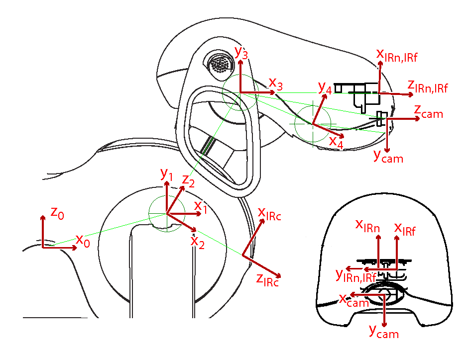
The position of a point of interest must be described relative to some reference frame, defined by x, y, and z axes. In the stick figures above, the origin of the base reference frame is shown as a green point at the center of the body. In the diagram at right, the base frame is reference frame 0. Notice that the x0 axis points forward, and the z0 axis points up.

For convenience, each chain has an associated series of reference frames for each of its joints and links. These frames are designated by number when invoking the kinematic functions, but we will refer to them using symbolic names instead. The names follow the same "offset" convention we use to refer to the joints themselves. So reference frame 1 in the diagram, which is located at the head tilt joint, is referred to symbolically as HeadOffset+TiltOffset. You can see that its orientation differs from the base reference frame: the x1 axis points forward, but it's the y1 axis that points up. The head tilts about the z1 axis. (Tekkotsu follows the Denavit-Hartenberg convention, so all joints move about their reference frame's z axis.) A joint reference frame does not rotate with its joint, so the x1, y1 and z1 axes remain fixed with respect to the base frame when the head tilts up or down.

The next joint in the head chain is the pan joint. The pan joint reference frame has its origin at the same point as the tilt joint. Its x2 and z2 axes rotate with the tilt angle (but not the pan angle). In this reference frame, referred to as HeadOffset+PanOffset, the head pans about the z2 axis.

The nod joint's reference frame is referred to as HeadOffset+NodOffset, and its x3 and y3 axes rotate with the tilt and pan angles (but not the nod angle). The head nods about the z3 axis.

At the distal end of the head chain is an additional reference frame corresponding to the camera rather than a joint, so it has a special name: CameraFrameOffset. Similarly, the chains for the three IR sensors end in joints named NearIRFrameOffset, FarIRFrameOffset, and ChestIRFrameOffset. Distance from an IR sensor corresponds to depth along the z axis (zIRn, zIRf, or zIRc, respectively.)

In addition to the joint reference frames, which do not rotate with their corresponding joints, Tekkotsu also provides a set of link reference frames whose axes have the same origin point, but do rotate with their joints. The names are the same as the joint reference frame names. You specify which kind of reference frame to use, joint or link, in the name of the function you call, e.g., jointToBase vs. linkToBase.

Converting Between Reference Frames

Transformation matrices convert points from one reference frame to another. Functions to compute these transformation matrices are provided by the Kinematics class. The most elementary of these, linkToBase, converts from an arbitrary link reference frame to the base frame. The inverse transformation is computed by baseToLink. Tekkotsu provides for conversion between reference frames on arbitrary chains. The general function is linkToLink.

The global variable kine holds a Kinematics instance whose joint angles are determined from current world state values, udpated automatically from the robot's sensors. We can use this instance to compute various reference frame transformations. Let's start with the simplest possible transformation:

cout << "Transform Base to Base:" << endl;
cout.precision(3);
cout << setw(7) << kine->jointToBase(BaseFrameOffset) << endl;

Since we are asking for a transformation from the base frame to itself, this should print out the identity matrix:

Transform Base to Base:
  1.000   0.000   0.000   0.000
  0.000   1.000   0.000   0.000
  0.000   0.000   1.000   0.000
  0.000   0.000   0.000   1.000

The rotational submatrix (shown in red) is a 3x3 identity matrix, the translational component (shown in blue) is zero, and the entire transformation matrix is a 4x4 identity matrix.

  Now consider the transformation from the tilt to the base reference frame, i.e., from reference frame 1 to reference frame 0 on the head chain. The table at left gives the full definition of the head, mouth, and IR chains. The notation indicates that reference frame 1 (tilt) is defined with respect to reference frame 0 (base), with an x offset of 67.5 cm and z offset of 19.5 cm.

The pan joint reference frame has the same origin as the tilt joint, so the x,y,z offsets from reference frame 2 to reference frame 1 are all zero. The nod joint (reference frame 3) is offset 80 mm along z2, the pan joint reference frame's z axis. The camera reference frame (cam) is defined with respect to reference frame 3 (nod), with an x offset of 81.06 cm and y offset of -14.6 cm.

Exercise: Examining Transformation Matrices

The relationship between reference frame 1 (tilt) and the base frame is fixed, because the base frame is a non-moving joint. So the transformation matrix from tilt to base should be the same no matter what posture the head is in. Let's see:

The code below computes both joint and link transformation matrices, so you can compare them. Each time DstBehavior is activated it will use the current joint angles to compute the matrices. Note that this behavior automatically deactivates itself, by calling DoStart from within DoStop.

#ifndef INCLUDED_DstBehavior_h_
#define INCLUDED_DstBehavior_h_
 
#include <iostream>
#include <iomanip>

#include "Motion/Kinematics.h"
#include "Shared/newmat/newmatio.h"
#include "Shared/WorldState.h"

class DstBehavior : public BehaviorBase {

public:
  DstBehavior() : BehaviorBase("DstBehavior") {}
 
  virtual void DoStart() {
    BehaviorBase::DoStart();
    std::cout << getName() << " is starting up." << std::endl;
    cout.precision(3);
    
    const float headtilt = state->outputs[HeadOffset+TiltOffset];
    std::cout << "Head tilt is " << headtilt * 360/(2*M_PI) << " degrees." << std::endl;

    NEWMAT::Matrix Ttiltj(kine->jointToBase(HeadOffset+TiltOffset));
    NEWMAT::Matrix Ttiltl(kine->linkToBase (HeadOffset+TiltOffset));
    std::cout << "tilt jointToBase= " << std::endl << setw(7) << Ttiltj << std::endl;
    std::cout << "tilt linkToBase=  " << std::endl << setw(7) << Ttiltl << std::endl;
    DoStop();
  }
 
  virtual void DoStop() {
    std::cout << getName() <<" is shutting down." << std::endl; 
    BehaviorBase::DoStop();
  }

protected:  // Dummy functions to satisfy the compiler
  DstBehavior(const DstBehavior&);
  DstBehavior& operator=(const DstBehavior&);

};

#endif

The code above follows the Tekkotsu kinematics convention of assigning transformation matrices names beginning with uppercase T. Later we'll create representations for points; their names begin with uppercase P. To experiment with the above behavior:

  1. Compile the behavior and start the robot.
  2. Open a telnet connection to the robot on port 59000.
  3. In ControllerGUI, go to "Root Control > Mode Switch > DstBehavior".
  4. Click the "Add" button in the ControllerGUI window, and click "OK" in the dialog box. This adds "DstBehavior" as a script you can invoke from anywhere in the menu system via the ControllerGUI's Scripts box.
  5. Go to "Root Control > File Access > Posture Editor".
  6. Turn off the Emergency Stop so the robot is free to move.
  7. In the Posture Editor, select NECK:tilt, type a value of 0 in the "Send Input" box, and hit return. This should cause the head to move upright, to a tilt value of 0 degrees.
  8. Now double click on "DstBehavior" in the scripts menu. Notice that the measured head tilt is not exactly 0 degrees, but close. The error should be at most a few degrees.
  9. Set the NECK:tilt value to -0.5236 radians (30 degrees downward).
  10. Double click on DstBehavior again and observe the results.
  11. Turn on Emergency Stop mode, grasp the head, and gently move it to a new position. Double click on DstBehavior again and observe the results.

Let's look at the output from the above exercise. First, for a zero degree tilt angle we should see the following:

DstBehavior is starting up.
Head tilt is 1.25 degrees.
tilt jointToBase=
  1.000   0.000   0.000  67.500
  0.000   0.000  -1.000   0.000
  0.000   1.000   0.000  19.500
  0.000   0.000   0.000   1.000

tilt linkToBase=
  1.000  -0.022   0.000  67.500
  0.000   0.000  -1.000   0.000
  0.022   1.000   0.000  19.500
  0.000   0.000   0.000   1.000

DstBehavior is shutting down.
The tilt frame and the base frame have the same orientation, but two of the axes are switched. In the tilt frame the y1 axis points up, while in the base frame it's the the z0 axis that points up. And in the tilt frame the z1 axis points to the left, while in the base frame the y0 axis points to the right. So the rotation submatrix above is a permutation of the identity matrix, with a sign flip in the second row. Note that the translational component of the transformation matrix (shown in blue) exactly matches the values in the "ERS-7 Head" table above.

Since the angle of the tilt joint is close to zero, the linkToBase transformation matrix matches the jointToBase matrix. Any difference between their rotational components (green vs. red), e.g., the green values of +/-0.022 shown above, is due to the head tilt value not being precisely 0.000.

Now let's use the Posture Editor to tilt the head down by 30 degrees and see what happens:

DstBehavior is starting up.
Head tilt is -29.5 degrees.
tilt jointToBase=
  1.000   0.000   0.000  67.500
  0.000   0.000  -1.000   0.000
  0.000   1.000   0.000  19.500
  0.000   0.000   0.000   1.000

tilt linkToBase=
  0.871   0.492   0.000  67.500
  0.000   0.000  -1.000   0.000
 -0.492   0.871   0.000  19.500
  0.000   0.000   0.000   1.000

DstBehavior is shutting down.
The jointToBase transformation matrix is the same as before, since the tilt joint reference frame does not move with the tilt joint. But the link reference frame does, so the linkToBase transformation matrix now indicates a rotation of -30 degrees in the x0-z0 plane, shown in fuchsia above. You can verify that cos(-30o) is 0.866, and sin(-30o) is 0.500, closely matching the matrix values. (The discrepancy reflects the measured head angle being only -29.5 degrees in this example.)

Explore more:

  1. Modify the above demo program to use reference frame 2 (the pan joint) instead of reference frame 1. If the tilt and pan values are both zero, what will the transformation matrix returned by jointToBase(HeadOffset+PanOffset) look like? (You should be able to figure this out on paper.)
  2. Try varying just the tilt value or just the pan value, leaving the other joint at zero. How do the joint and link transformation matrices printed out by your modified program change as you move one joint vs. the other?
  3. Review the documentation for the Kinematics class.
  4. Multiplication of transformation matrices:
  5. For nonzero values of head tilt, the jointToJoint function produces very different results (not a mere sign change or matrix inverse) when mapping from tilt to nod vs. from nod to tilt. Why is that? (Hint: which joint moves in the other joint's reference frame?)
  6. Show how to extract information from a transformation matrix to derive the vector, in the tilt joint reference frame, from the center of the tilt joint to the center of the nod joint. What is the value of this vector when the head is tilted straight up (zero degrees)? What is the value when the head is tilted down by 30 degrees?

Interest Points

Tekkotsu provides a variety of pre-defined interest points on the head, legs, and body. These points are accessed by name, and their coordinates can be returned in any desired reference frame.

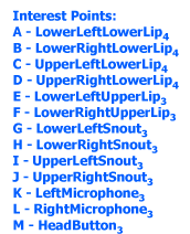
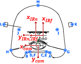
The diagrams above show the interest points defined for the ERS-7 head. For example, interest point "HeadButton" is located at the top of the head, at point M on the diagram. It is defined in link reference frame 3. This indicates that the HeadButton interest point moves with the head tilt, pan, and nod, but not with jaw motion (reference frame 4). Points A-D in the diagram are located on the lower jaw, and do shift with jaw motion; they are defined in reference frame 4.

To retrieve the current location of the head button in base frame coordinates, you would write getJointInterestPoint(BaseFrameOffset,"HeadButton") or getLinkInterestPoint(BaseFrameOffset,"HeadButton"). (The two are equivalent for the base frame.) Notice that the interest point name is passed as a string. This string can also be a comma-separated list of interest points, in which case their coordinates are averaged together. So to get the coordinates of the tip of the lower lip in the reference frame of the camera, you would write getJointInterestPoint(CameraFrameOffset,"LowerLeftLowerLip,LowerRightLowerLip"). The result is a 4x1 ColumnVector.

Exercise: Measuring Distance Using Interest Points

The program below prints out the distance between the two front paws. It does this by calculating the coordinates of two paw interest points in the base frame. It then subtracts one from the other. The distance is the norm of the result.

This behavior uses a recurring timer established by DoStart to wake up once each second. The inter-paw distance is computed and printed in processEvent. The distance is measured between LowerInnerMiddleLFrShin and LowerInnerMiddleRFrShin, both of which are marked as B in the leg interest point diagram discussed in the next section.

#ifndef INCLUDED_DstBehavior_h_
#define INCLUDED_DstBehavior_h_
 
#include <iostream>
#include <iomanip>

#include "Events/EventRouter.h"
#include "Motion/Kinematics.h"

class DstBehavior : public BehaviorBase {

public:
  DstBehavior() : BehaviorBase("DstBehavior") {}
 
  virtual void DoStart() {
    BehaviorBase::DoStart();
    std::cout << getName() << " is starting up." << std::endl;
    erouter->addListener(this,EventBase::timerEGID);
    erouter->addTimer(this,1,1000,true);
  }

  virtual void DoStop() {
    std::cout << getName() <<" is shutting down." << std::endl; 
    BehaviorBase::DoStop();
  }

  virtual void processEvent(const EventBase&) {
    NEWMAT::ColumnVector Pleftpaw = 
      kine->getJointInterestPoint(BaseFrameOffset,"LowerInnerMiddleLFrShin");
    NEWMAT::ColumnVector Prightpaw = 
      kine->getJointInterestPoint(BaseFrameOffset,"LowerInnerMiddleRFrShin");
    const float distance = (Pleftpaw-Prightpaw).NormFrobenius();
    std::cout.setf(ios::fixed);
    std::cout.precision(1);
    std::cout << "Inter-paw distance is " << setw(5) << distance << " mm." << std::endl;
  }
 
protected:  // Dummy functions to satisfy the compiler
  DstBehavior(const DstBehavior&);
  DstBehavior& operator=(const DstBehavior&);

};

#endif

Run this code with Emergency Stop turned on so you can move the AIBO's front legs together and apart, and observe how the computed distance changes. What is the minimum possible distance you can achieve between the two paws?

Body and Leg Descriptions

The four leg chains have five reference frames each: the base frame, the shoulder joint (which moves the leg forward or back), the elevator joint (which moves the leg in or out), the knee joint, and the ball of the foot. The diagram excerpt below left (click for full diagram) shows the naming scheme for the axes: f and h denote fore and hind legs; L and R denote left and right legs. The naming scheme for the joints themselves follows the "offset" convention discussed previously. So, for example, the right hind leg's elevator joint is named RBkLegOffset+ElevatorOffset, and it rotates about the zh2R axis to move the leg closer to or further away from the body.
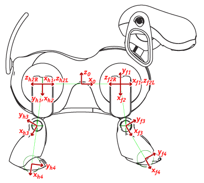

Axis subscripts f and h indicate fore and hind legs;
L and R indicate left and right legs.
Italics in table at right indicate estimated values.

The kinematic chain and reference frame numbers for the right hind leg are shown in the stick figure above right. Note that the origins of the shoulder joint reference frames (reference frame 1 of each chain) are on the midline of the body. So the two hind shoulder joint reference frames have the same origin and orientation, and are shown in the left diagram as xh1,yh1 with no L/R suffix.

Since the balls of the feet do not contain joints, their reference frames have special names based on PawFrameOffset and LegOrder_t. The reference frame for the ball of the right hind leg is named PawFrameOffset+RBkLegOrder.

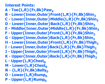
Body and leg interest points are shown in the diagram excerpt below (click for full diagram.) The naming scheme in the table exploits the multiple symmetries of the body to compactly express the names of 94 interest points. For example, point H indicates 8 interest points. One of these, the lower outer front edge of the left front leg's thigh, is named "LowerOuterFrontLFrThigh".

Stare At Paw Demo

In this exercise we will have the AIBO moves its head to keep its left front paw in the center of the camera image. We can move the head using the lookAtPoint method of HeadPointerMC, which accepts x, y, and z coordinates in the base reference frame. All we need to do is calculate the coordinates of the tip of the paw in the base frame. This is easily accomplished using getJointInterestPoint. The interest point name is "ToeLFrPaw".

This program uses two motion commands. One relaxes the left front leg (by zeroing the joint forces) so you can move the leg easily. The other moves the head to keep it 30 mm from the coordinates we calculate for the left front paw. Each time the world state is updated, new joint angles are available; a sensor event will be thrown which we can detect with processEvent. We respond by calling getJointInterestPoint to get the new paw coordinates in the base frame, and then update the headpointer motion command.

#ifndef INCLUDED_DstBehavior_h_
#define INCLUDED_DstBehavior_h_
 
#include "Events/EventRouter.h"
#include "IPC/SharedObject.h"
#include "Shared/WorldState.h"
#include "Motion/MotionManager.h"
#include "Motion/MMAccessor.h"
#include "Motion/Kinematics.h"
#include "Motion/HeadPointerMC.h"
#include "Motion/PIDMC.h"

class DstBehavior : public BehaviorBase {

private:
  MotionManager::MC_ID relax_id, headpointer_id;
  static const float head_to_paw_distance = 30.0;  // millimeters

public:
  DstBehavior() : BehaviorBase("DstBehavior"), 
		  relax_id(MotionManager::invalid_MC_ID),
		  headpointer_id(MotionManager::invalid_MC_ID){}
 
  virtual void DoStart() {
    BehaviorBase::DoStart();
    std::cout << getName() << " is starting up." << std::endl;
    relax_id = motman->
      addPersistentMotion(SharedObject<PIDMC>(LFrLegOffset,LFrLegOffset+JointsPerLeg,0.0));
    headpointer_id = motman->addPersistentMotion(SharedObject<HeadPointerMC>());
    erouter->addListener(this,EventBase::sensorEGID);
  }

  virtual void DoStop() {
    std::cout << getName() <<" is shutting down." << std::endl; 
    motman->removeMotion(relax_id);
    relax_id = MotionManager::invalid_MC_ID;
    motman->removeMotion(headpointer_id);
    headpointer_id = MotionManager::invalid_MC_ID;
    BehaviorBase::DoStop();
  }

  virtual void processEvent(const EventBase&) {
    NEWMAT::ColumnVector Ptarget = kine->getJointInterestPoint(BaseFrameOffset,"ToeLFrPaw");
    MMAccessor<HeadPointerMC>(headpointer_id)->
      lookAtPoint(Ptarget(1),Ptarget(2),Ptarget(3),head_to_paw_distance);
  }
 
protected:  // Dummy functions to satisfy the compiler
  DstBehavior(const DstBehavior&);
  DstBehavior& operator=(const DstBehavior&);

};

#endif

Camera view of paw To run this demo, start up DstBehavior and turn off Emergency stop mode. Press the RawCam button in the ControllerGUI to turn on the camera viewer . Then grasp the left front leg and move it slowly. The head should follow the paw. The paw should remain roughly centered in the camera's field of view, as in the image at right.

A more elaborate version of this demo, which allows you to select which paw to stare at by pressing the button on the ball of the foot, is included in Tekkotsu. You can find it at "Root Control > Mode Switch > Kinematics Demos > New Stare At Paw".

Ground Plane Calculations

(To be written later.)

Prev: Vectors
Up: Contents
Next: Inverse kinematics

Last modified: Wed Mar 17 05:36:45 EDT 2010