This is a circuit
for a simplified meter - a no bells and whistles version for home construction
and use in basic auditing or just to experiment with. I've cut the circuit
back to basics using a standard wheatstone bridge and instrumentation amp
circuit. The arrangement with diodes D1 and D2 is just to stop the needle
moving too far when the sensitivity is adjusted with the needle at 1/3rd
of a dial. C1 and C2 cut out radio signals picked in the leads and wiring.
The LED is there as just a primitive voltage stabilizer. The bridge circuit
can be optimized for dual cans, solo or fingertip electrodes by varying
resistor R1.

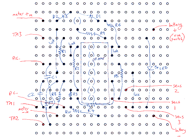
Here's the layout diagram
for 0.1" veroboard. I'd suggest leaving space for mounting and maybe 8
rows at the top if you're thinking of adding better voltage stabilization
with another chip later.
Component list:
R1 22k for 2 can use, 43k
for solo, 62k for fingertip electrodes.
R2,4,5,7 15k
R3,8 68k
R6,9 10k
R10 6.8k
C1,2 1nF
Led small red
Meter movement 100µA
F.S.D
Op amp LM324, MC33174. Most
quad op amps should work ok.
D1,2 small signal diodes,
silicon
VR1,2 50k linear.