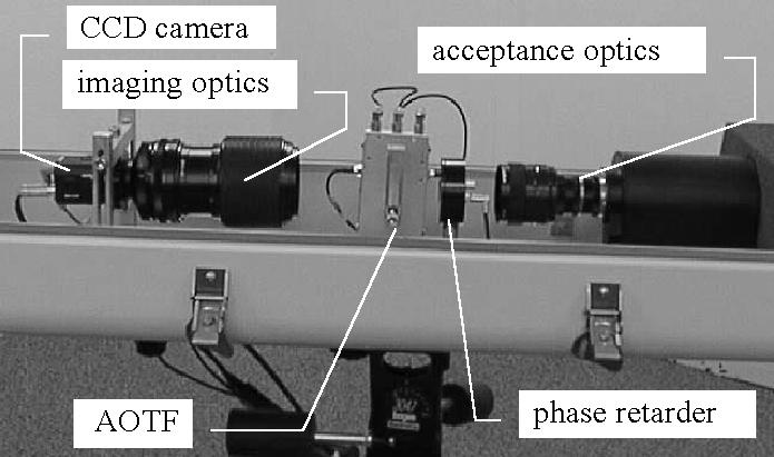
The AOTF crystal performs the spectral filtering, and the phase retarder works in conjunction with the AOTF crystal to accomplish polarimetric filtering.
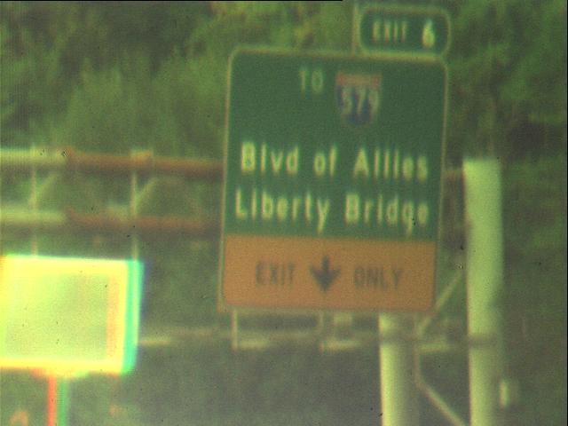
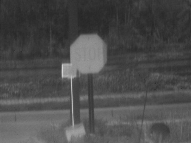
One obvious concept involves applying a narrowband spectral filter to the image while sweeping the center wavelength of the filter over the range of the camera. For example, one might vary the wavelength from 400 to 800 nanometers in increments of 10 nanometers, thereby generating 41 bands. The output of this spectral sweep is an image cube with axes in x, y, and wavelength. It is interesting to note that most objects do not reflect light over just a narrow range of wavelengths. Instead, they reflect light over all wavelengths, perhaps reflecting more at some wavelengths. As a result, a stop sign is visible in all the images, but is brighter in wavelengths in the red area of the spectrum.
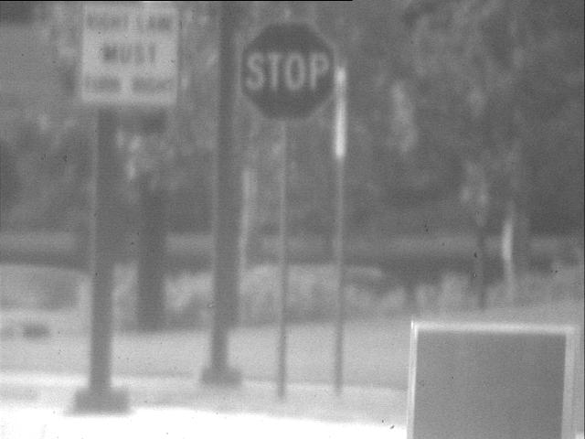
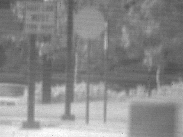
Unfortunately, performing a spectral sweep takes time, which means that objects may move significantly between the instant that the first image is captured and the moment the sweep is completed. At the other extreme is a strategy called band alternation. In this case, two (or a few) bands are rapidly alternated.
The AOTF is not limited to simple narrowband filters, though. More complex waveforms can be generated using an arbitrary waveform generator. With these waveforms, complex filtering operations, such as those performed by the human eye, could be executed in a single frame.
Another possible control strategy is to combine the slow spectral sweep with the fast alternation strategy. The slow sweep can be performed infrequently, and the results analyzed to determine the bands or waveforms to be used in the alternation strategy, which is then executed in a fast loop. In this way, one can adapt the strategy dynamically using all the available spectral information without the penalty of constantly executing a spectral sweep.

 Colorization serves two purposes. First, it allows us to visually verify
that the camera is indeed accurately capturing the spectral content of a
scene. Merely looking at a series of monochrome images gives no real feel
for this content. Second, since we can arbitrarily adjust the color
sensitivity curves, we can simulate a variety of real and artificial
systems, including ccd cameras and human eyes.
Colorization serves two purposes. First, it allows us to visually verify
that the camera is indeed accurately capturing the spectral content of a
scene. Merely looking at a series of monochrome images gives no real feel
for this content. Second, since we can arbitrarily adjust the color
sensitivity curves, we can simulate a variety of real and artificial
systems, including ccd cameras and human eyes.
 Our interest in the AOTF camera lies in its ability to perform terrain
classification. At CMU, the Unmanned Ground Vehicle (UGV) project has
demonstrated autonomous planning, mapping, and off-road navigation skills
using the NavLab II, a modified Army HMMWV. But despite its impressive
capabilities, NavLab II is unable to distinguish between rocks and tall
grass, trees and hillsides, or even mud and hard ground. As a consequence,
the vehicle plans and navigates conservatively, avoiding all objects that
may be potential hazards. By identifying and classifying the different
types of terrain in a scene, we reduce the number of false positive
obstacles, such as tall grass, as well as false negatives, such as water and
mud.
Our interest in the AOTF camera lies in its ability to perform terrain
classification. At CMU, the Unmanned Ground Vehicle (UGV) project has
demonstrated autonomous planning, mapping, and off-road navigation skills
using the NavLab II, a modified Army HMMWV. But despite its impressive
capabilities, NavLab II is unable to distinguish between rocks and tall
grass, trees and hillsides, or even mud and hard ground. As a consequence,
the vehicle plans and navigates conservatively, avoiding all objects that
may be potential hazards. By identifying and classifying the different
types of terrain in a scene, we reduce the number of false positive
obstacles, such as tall grass, as well as false negatives, such as water and
mud.
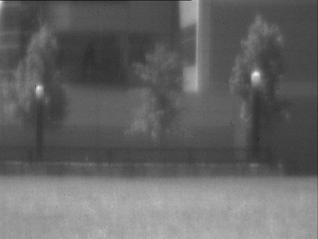
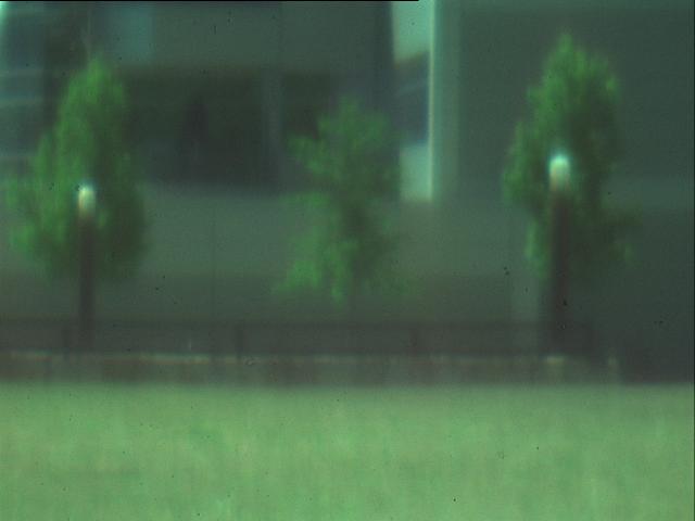
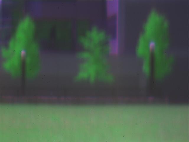
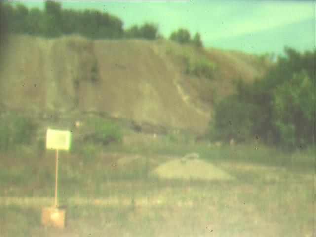
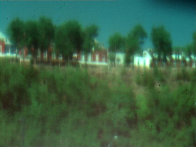
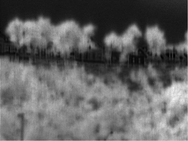
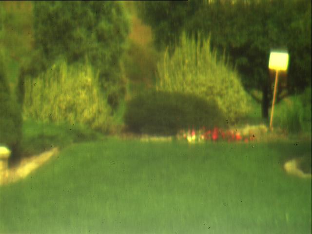
Terrain classification is difficult with a monochrome camera because different terrain types may produce the same image intensity. A color camera alleviates this problem somewhat, but the off-road terrain in which we are interested often contains only muted colors, which are difficult to distingish using only the red, green, and blue components of the scene. The AOTF camera provides us with fine-grain measurements over the full visible spectrum as well as the near infrared.
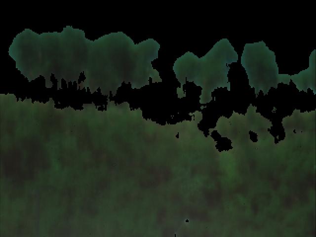
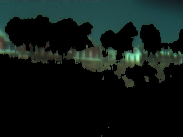
By taking the ratios of intensities of two bands, we can discriminate vegetation from non-vegetation. The result of this computation can be used in its raw form as a confidence measure or as a thresholded image. By combining the thresholded image with the colorization algorithm, we can selectively eliminate all vegetation or all non-vegetation from a scene.


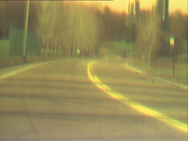
 We have also experimented with the control of the polarimetric filtering
capability of the AOTF camera. In one experiment, we tested whether
the system could detect regions of high glare on a road. Frequently, glare on a
road is due to water or icy regions. By detecting glare, we could provide
an early warning system to drivers or an additional input to autonomous
vehicles. In the example below, the top two images were obtained by
adjusting the retarder for minimum and maximum glare. The regions of glare
are then detected simply by subtracting the two images. As with vegetation
detection, a binary output can be obtained by thresholding the resulting
image. This algorithm demonstrates that our system can accomplish difficult
computer vision tasks using simple algorithms. The problem has been made
easier by transferring the complexity into the hardware.
We have also experimented with the control of the polarimetric filtering
capability of the AOTF camera. In one experiment, we tested whether
the system could detect regions of high glare on a road. Frequently, glare on a
road is due to water or icy regions. By detecting glare, we could provide
an early warning system to drivers or an additional input to autonomous
vehicles. In the example below, the top two images were obtained by
adjusting the retarder for minimum and maximum glare. The regions of glare
are then detected simply by subtracting the two images. As with vegetation
detection, a binary output can be obtained by thresholding the resulting
image. This algorithm demonstrates that our system can accomplish difficult
computer vision tasks using simple algorithms. The problem has been made
easier by transferring the complexity into the hardware.
| Last modified January 28, 1998 Daniel Huber ( dhuber@cs.cmu.edu) |