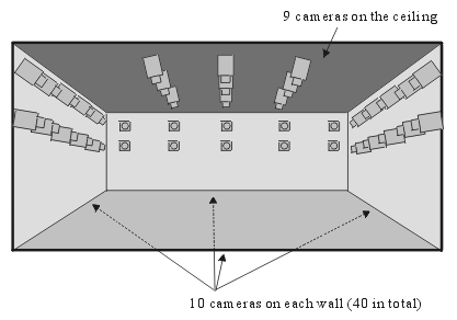
Figure 1 : Camera placement in the 3D Room.

Figure 2: Panoramic view of 3D Room in CMU.
The 3D Room:
Digitizing Time-Varying 3D Events by
Synchronized Multiple Video Streams
Takeo Kanade, Hideo Saito, Sundar Vedula
CMU-RI-TR-98-34
The Robotics Institute
Carnegie Mellon University
Pittsburgh, Pennsylvania 15213
December 28, 1998
The "3D room" is a facility for 4D digitization - capturing and modeling a real time-varying 3D event into a computer. On the walls and ceiling of the room, a large number of cameras (at this moment 49 of them) are mounted, all of which are synchronized with a common signal. A PC-cluster computer system (consisting of 17 PCs at this moment) can digitize all the video signals from the cameras simultaneously in real time as uncompressed and unlossy full frame images with color (640x480x2x30 byte per seconds). The images thus captured are used for research on Virtualized Reality(TM)[1-6]. This digital 3D Room is a natural outgrowth of our previous "3D Dome" [1,2], which was built in 1994 and has been used for a similar purpose, but was based on analog VCRs and thus limited to offline applications. This document describes the current 3D Room as of December 1998 - design, components and capabilities - built at CMU Robotics Institute.
II. THE CMU 3D ROOM- Configuration
The CMU 3D Room is 20 feet (L) x 20 feet (W) x 9 feet (H). As shown in figure 1, 49 cameras are distributed inside the room: 10 cameras are mounted on each of the four walls, and 9 cameras on the ceiling. Figure 2 shows a panoramic view of the 3D Room.
Figure 1 : Camera placement in the 3D Room.
Figure 2: Panoramic view of 3D Room in CMU.
Figure 3 shows an overview of the digitizing system. All of the 49 cameras are synchronized by a single synchronizing signal. The S-Video output from each camera, consisting of two separate signal lines of intensity (Y) and color difference (C), is mixed with the output of VITC signal generator, so that the time code is embedded onto intensity signal of the S-Video for time frame labeling. The computing system consists of one Control PC and a cluster of 17 digitizing PCs. Each digitizing PC contains 3 digitizer cards, and can simultaneously digitize up to 3 video inputs. The Control PC controls the 17 digitizing PCs for coordinating overall setup and timing for the whole digitization process.
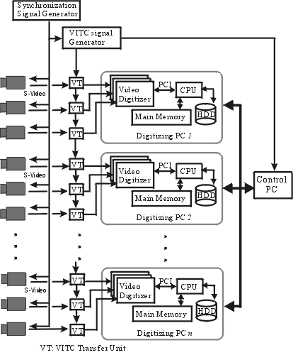
Figure 3: The digitization system of the 3D Room (ver.1, Dec. 98) consists of synchronized 49 cameras, VITC signal generators, 17 Digitizing PCs and one Control PC.
The detailed specifications of individual system components are as follows:
Camera
VITC Unit Hardware
The VITC signal, which encodes address of the time frame into a video signal, is embedded onto every video camera signal, so that every image frame can be labeled by the time frame.
PC Hardware
PC Software
The analog video signal format is S-Video. The digital image format we use is YCrCb 4:2:2. The intensity image of Y is digitized in full size of 640x480 while color components, Cr and Cb, are digitized in half size of 320x480; in average, 2 bytes are used per pixel for representing the digitized image of YCrCb 4:2:2. Sampling color components in half resolution help reducing the data rate of digitization, and is acceptable because human visual perception is not as sensitive to the spatial resolution of color component. Also, most vision algorithms use mainly intensity information for the purpose of matching and registration.
The data rate per video channel is
This is well under the PCI bus burst transfer rate of 132 MBytes/sec., and well over the 7 to 9 MBytes/sec transfer rate of a simple hard disk media. Therefore as a simple and cost-effective solution we chose a method that uses real-time capturing into memory and off-line saving to the disks.
B) Capacity - Duration of Digitization
Each PC currently has 512MBytes memory. The total memory area available for storing digitized images is about 480MBytes after subtracting the system usage. The total number of images that can be stored in the memory is therefore
480MByte / (640x480x2 Byte) = 819 frames.
If three cameras are digitized in one PC, up to 819/3 = 273 frames can be captured per camera at one time. This capacity corresponds to 9.1 seconds of duration at 30 fps at full size frames. The digitization control program allows the user to choose smaller image formats or lower frame rates in order to extend the duration of digitization.
The control PC coordinates and monitors the whole digitization process, as well as providing the user interface. Figure 4 shows the interface window, through which a user can specify the digitization; frame rate, frame format , starting time, total duration, enabling/disabling of specific cameras, and so on. The current VITC timecode is displayed on the window, so the user can easily specify the starting timecode. Clicking the "Grab" button sets the timer to start the digitization, and while waiting, the control PC beeps at an interval of 1 second, like an ordinary camera's timer. Digitization starts at the specified time, and the beep turns to a continuous one till the end of digitization period. When the digitization is completed, each digitizing PC writes the image data out to a disk, and the control PC collects information from the digitizing PCs to verify if the whole digitization was done as specified without any missing, corrupted, or extra frames.

Figure 4 : Window of server program for contoroling digitization on all PCs. In this window, user can easily set every configuration for every camera.
The system performance has been verified by running 500 experi-ments, with each experiment involving a capture of 250 frames. On every experiment, the corrupt flag was checked, timecode was verified, both for consistency across all the cameras, and for regular increments between captured images. The stability of the system was satisfactorily verified.
We have constructed the 3D Room, a room with 49 cameras, whose output signals can be captured ) into a computer in real time as digital uncompressed and unlossy full frame images with color (640x480x2x30 byte per seconds. The 3D Room for Virtualized Reality [1-6] is a unique facility, and one of the first of its kind - modeling a time-varying real 3D event into a computer, as is and as its totality, and using the resultant models for manipulating, altering and rendering the reality. We intend to make this facility and the data sets from it available for the vision research community in the near future.
ACKNOWLEDGEMENT
The development of the 3D Room has been benefited by the work of Peter Rander, Makoto Kimura, Shigeyuki Baba, Ching Kai, and Peter Kioko. Intel Corporation, Sony Corporation and Matsushita Electric Industrial Company provided partial support for this project.
REFERENCES