Abstract
Shape Deposition Manufacturing (SDM) is a solid
freeform fabrication (SFF) process that incrementally builds up complex
parts by systematically combining material additive processes with material
removal processes. The advantages of each type of process are thus combined
such that novel structures can be fabricated with SDM that could not be
practically fabricated with either material additive or material removal
processes alone. Examples of such structures, which are relevant to Navy/DOD
applications, are described in this paper including a waterproof wearable
computer with embedded electronics, a composite steel/copper injection
mold tool, and a miniature turbine wheel assembly. In addition, this article
presents a novel implementation of a SDM system based upon the integration
of deposition apparatus (i.e., material additive process) with an existing
computer-numerically-controlled (CNC) milling machine (i.e., a material
removal process). Such an implementation is a cost-effective way to create
high-quality SFF machines.
1. Introduction
Most solid freeform fabrication (SFF) systems are
based upon a material additive, layered manufacturing method. Computer-aided-design
(CAD) models are first decomposed into thin cross-sectional layer representations,
then physical parts are built up in custom automated fabrication machines,
layer-by-layer, using material additive processes (1). Layers of sacrificial
structures are simultaneously built up to fixture and support the growing
shapes. While layered manufacturing facilitates rapid prototyping (e.g.,
quickly fabricating "models", as opposed to production parts) of arbitrarily
complex shapes, the resulting surface finish and accuracy, which are critical
factors for being able to fabricate functional parts, are compromised by
the "stair-steps" from layer-to-layer. High accuracy and quality surface
finishes, required for such applications as custom tooling, precision assemblies,
and structural ceramics, are best achieved with material removal processes
such as 3- and 5-axis computer-numerically-controlled (CNC) milling and
electrical discharge machining (EDM) machines.
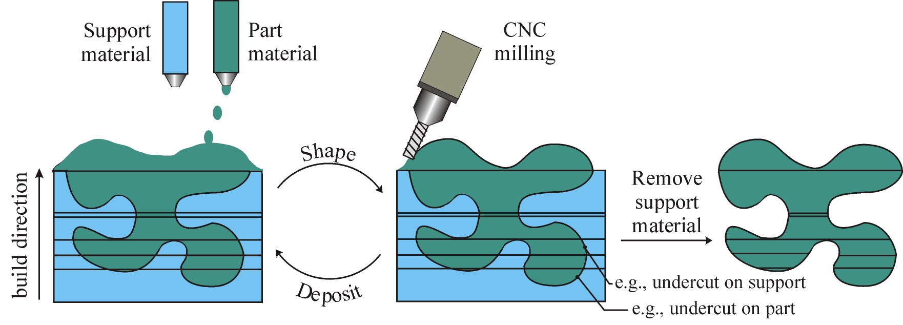
Shape Deposition Manufacturing (SDM) is a SFF process for which the original goal was to combine the advantages of geometry decomposition and material addition with the advantages of material removal processes (Figure 1). The basic SDM fabrication methodology is to deposit individual segments of a part, and of support material structure, as near net shapes, then machine each to net-shape before depositing and shaping additional material (2). This method takes advantage of the basic SDM decomposition strategy which is to decompose shapes into segments, or 'compacts', such that undercut features need not be machined, but are formed by depositing onto previously deposited and shaped segments. For example, undercut part features are formed by depositing onto shaped support material compacts, and vice-versa. In addition, the decomposition plan preserves the 3D-geometry information of the outer surface of each compact so that the desired shape of the CAD model can be accurately replicated when 5-axis machining is available. Each compact in each layer is deposited as a near-net shape using one of several available deposition processes that are described in subsequent sections. The thickness of each compact depends not only on the local part geometry, but also on deposition process constraints. After the entire part is built up, the sacrificial support material is removed to reveal the final part.

Another key issue for our research is how to implement SDM in a cost-effective fashion. Until recently, SDM operations have been executed by building up the parts on pallets and transferring them to individual operating stations using a robotic palletizing system (4). Robotic manipulation was used in order to create a flexible system, for an R&D environment, which could be easily modified in order to investigate alternative deposition, shaping or other intermediate processing operations. Such a system, however, is too expensive and large for general dissemination of this technology. The next section describes a novel, cost effective and compact implementation of SDM.
2. Integrated CNC Shaping and Deposition Machine
Commercialized SFF systems are customized machines,
and high performance SFF apparatus can be relatively expensive. As an alternative
to customization, or to robotic automation, we are exploring implementing
SDM by simply adding deposition apparatus directly to existing CNC milling
machines such as are typically found in machine shops throughout the world.
In addition to shaping operations, the CNC milling machine provides the
precision motion control required for deposition. When not being used for
SDM, such an integrated CNC deposition and shaping machine can still be
used as a conventional milling machine.
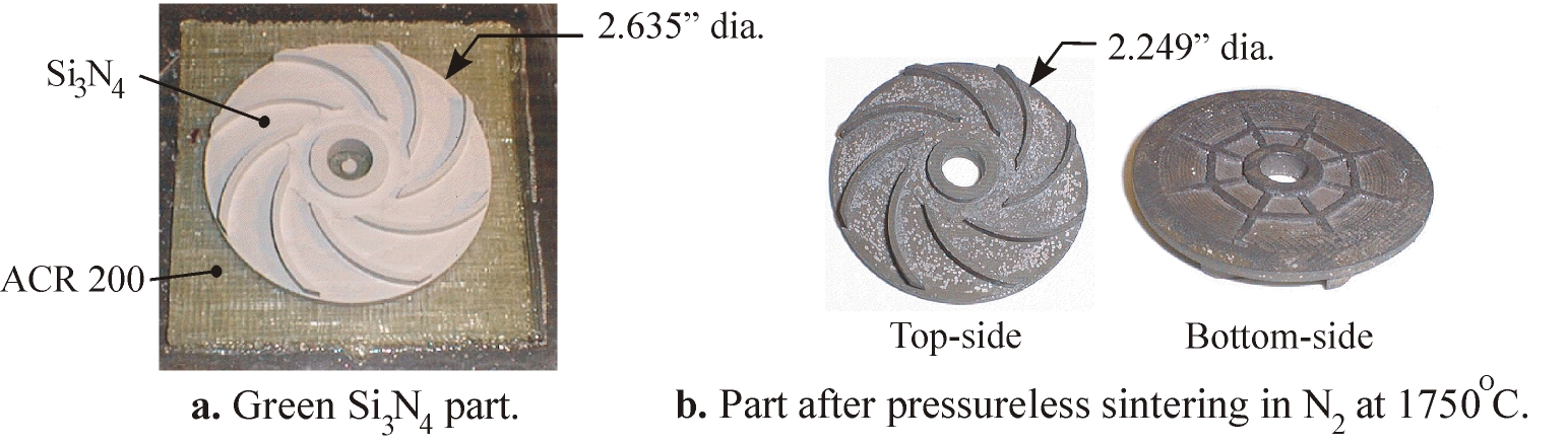
For one example, the integrated CNC deposition/shaping machine shown in Figure 3a is being used to investigate the fabrication of 'green' ceramic parts using an extrusion deposition process (5). Green materials, which are deposited by the extruder, are composed of ceramic powders densely bound in polymeric binders. After the green part is built up and removed from the machine, the binder is burned out in a furnace. Then, the part is sintered to fuse the powder to form the final ceramic part. The CNC machine is based upon a commercially available Fadal VMC-15 3-axis mill with an automatic tool changer carousel1. An Advanced Ceramics Research extruder2 is mounted on a pneumatically actuated slide that is attached to the Z-axis spindle housing of the CNC machine. The slide is retracted when the extruder is not in use (e.g., during machining operations) and lowers the extruder into the workspace during deposition operations. The extruder is used to deposit both support and part materials; currently, we manually switch extrusion tubes/nozzles preloaded with the different materials. Being able to quickly build complex ceramic parts is important for many military applications such as components for high-performance miniature turbine engines for drone aircraft.

An example of a 'green' ceramic part built on the integrated SDM machine is shown in Figure 4. The part material is silicon nitride, and the support material is ACR 200, a proprietary non-ionic, water-soluble, machinable thermoplastic. While this particular shape could have been cut directly from a block of 'green' ceramic stock, such conventional machining would require re-orienting, re-fixturing, and registering the part after the top-side has been cut in order to cut the bottom-side. Another advantage of SDM over conventional machining is that first depositing shapes in near-net, before machining, reduces the waste of costly materials.
3. Multi-Material (Heterogeneous) Structures
We believe that one of the most important roles
for SFF in the future will be to help manufacture heterogeneous product
designs. Several of these novel products that have been built with SDM
are described below. While conventional manufacturing methods could have
been used to fabricate these products, these methods would have required
additional time-consuming operations, including the need for custom fixturing
and tooling, complex assembly operations, and high-strength material joining
processes.
3.1. Steel/Copper Tooling
Injection molding is the process of forming plastic
parts by first flowing heated plastic into the cavity of a custom tool
(i.e., the cavity is in the shape of the part), then allowing the plastic
to cool down and solidify, and finally opening the tool to remove the part.
Injection molding is used to mass-produce plastic parts in quantities from
hundreds to millions of parts. SFF has been widely investigated for fabricating
injection mold tools with complex molding surfaces, as well as with conformal
internal cooling channels for thermal management. With SDM, even more advanced
tools can be fabricated composed of multi-materials such as steel/copper
composites. While steel provides strength and wear-resistance, copper's
superior heat transfer properties provides quick heat up and cool down
of the tool as well as uniform heating. For example, Figure 5a shows a
composite 316L stainless steel injection molding tool produced by SDM using
robotic-controlled laser welding and microcasting deposition processes
(7). One half of the tool, which is shown schematically in Figure 5b, has
four internal copper deposits for temperature equilibration. Both halves
of the tool have a "U"-shaped channel for water cooling during the molding
process. The channels were formed by sacrificial copper, which was removed
by etching in nitric acid. Portions of the cavities contained small features
that could not be cut with end mills and these were finished with EDM.
In this tool, the steel was deposited with a laser welding process (Figure 5c). A 2.4 kW CW Nd:YAG laser scans over the substrate and a melt pool forms into which metal powder is injected (Figure 5c). The injected powder fuses onto the substrate, leaving a bead of deposited material in its wake. While this laser welding process is very precise, in comparison with conventional welding methods, it cannot effectively deposit copper due to copper's high reflectively. Therefore, microcasting was used to deposit the copper (Figure 5d). Microcasting is a non-transferred welding process that deposits discrete droplets of super-heated molten metal (6).

In addition to creating steel/copper structures, the laser system has also been used to deposit INVARTM, a low coefficient-of-thermal-expansion (CTE) nickel alloy, onto copper that was previously deposited onto steel. Such multi-material structures will have significant advantages in a wide variety of military applications. For example, in dies used for forming composite airfoils (e.g., for airplane and boat bodies), INVAR provides a closer match to the CTE of composite materials, thus resisting deforming the material during molding operations.
Ideally, the transition between different materials should be functionally graded, e.g., having a gradual change in material composition from one material to the next material. The laser system is particularly suitable for producing functional-gradient, multi-material parts because different materials can be continuously alloyed during the build process by simply mixing the powders which are fed to the melt pool.
3.2. Embedded Electronics
Another example of a heterogeneous design is an
embedded electronic device fabricated by building up a nonconductive housing
package and simultaneously embedding and interconnecting electronic components
within the housing. With this approach it is feasible to relatively quickly
fabricate compact, rugged, customized computer modules in small lot sizes.
This capability is particularly well suited for military applications to
manufacture mission-specific, conformal shaped 'smart' devices such as
wearable computers tailored for an individual soldier or a small military
unit. These computers might store maps, equipment descriptions, help to
log data, or provide communication links.
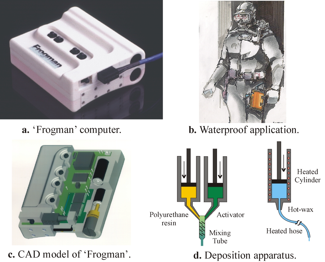
For one example, the 'Frogman' shown in Figure 6a and 6b is a waterproof computer that can store maps for navigational aids, or detailed assembly drawings for service, maintenance, or field operations. The graphical information, which is stored on Personal Computer Memory Card International Association (PCMCIA) cards, is displayed on a heads-up display (Figure 6c). A conformal shaped rear surface was also required so that the unit could be comfortably strapped to a diver's leg. The device is built up in layers of polyurethane (PU) and sacrificial wax. The PU is deposited as a 2-part thermoset (left side of Figure 6d). The wax can be extruded with a conventional hot-glue gun (right side of Figure 6d), or thick layers can be poured from a hot-melt pot. The fabrication details, including component embedding and interconnection are described in detail in (8). The important points are that custom tooling was not required to manufacture the Frogman and that embedding facilitates waterproofing.
4. Integrated Assemblies
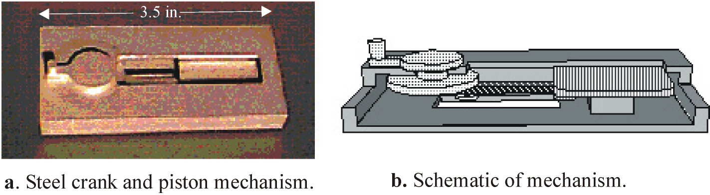
SDM has also been used to build up simple assemblies in a single operation. As an assembly is being built up, its individual components are separated by and encased within sacrificial support material. After the assembly structure has been completely built up, the sacrificial material is removed, freeing the components to move with respect to each other. For example, SDM was used to create the steel crank mechanism shown in Figure 7. In this mechanism, a piston is connected to a crankshaft with a connecting rod. Turning the crank causes the piston to move back and forth in its chamber. The mechanism components are 316L stainless steel, deposited with laser welding, and the sacrificial support material was microcast copper.
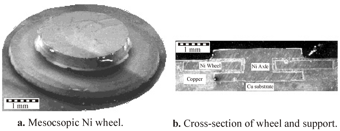
In SDM, mesoscopic structures are built up using sputtering and electro-plating deposition processes, and shaped with micro CNC or EDM machining. For one example, the 1.1mm high nickel structure shown in Figure 8a consists of a wheel (5mm dia., 0.3mm thick) which is permanently mounted on a nickel axle (1mm dia.). The scanning electron microscopy (SEM) photograph in Figure 8b shows a cross-section of the wheel and axle before removal of copper support structure.
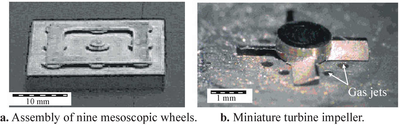
Additional examples of novel SDM mesoscopic integrated assembles are shown in Figure 9. Figure 9a is a nickel substrate carrying nine mesoscopic wheels. This structure suggests the possibility for building massively parallel miniature machinery. Figure 9b shows a 130mm thick microturbine impeller that rotates at high speeds when air is passed through the gas jets. This structure establishes the feasibility of building assembled devices with clearances on the order of less than 20mm.
5. Discussion
SFF has been successfully used within the limited realm of Rapid Prototyping. However, as SFF processes improve and are able to build functional, engineering models, SFF will be used for mass customization, i.e., customers able to order products in small-lots (as small as one) customized for their specific needs. Such 'mass-customization' will be attractive for not only consumer and commercial markets, but also for defense industries as a "dual-use" technology for creating products tailored to individual soldiers needs, as well as for cost effective tooling for manufacturing defense systems. In addition, by opening up the design space, novel designs, inaccessible with conventional manufacturing techniques, will be possible. One class of such novel designs is heterogeneous structures, such as embedded electronics, and another class is integrated assemblies as described in this article. For heterogeneous structures to be practical, however, streamlined CAD systems will be required which enable concurrent representation and manipulation of geometry, material and embedded components. Other possible novel designs will involve functional gradient structures such as ceramic to metal parts or graded metal to metal structures allowing the transition from highly thermally conductive regions, inside, to tough surfaces on the outside of a part. Beyond these novel applications of SFF, it is hard to predict where exactly this will lead to when creative people have access to SFF technology. Undoubtedly, the creation of products that no one has even conceived of as yet will be one of the likely outcomes.
Acknowledgments
This work has been supported by the ONR, DARPA, and NSF. The authors
acknowledge the following individuals for their contributions in creating
the systems and the parts built with these systems described in this article:
Gennady Neplotnik, Larry Schultz, Robert Merz, Alexander Cooper, John Fessler,
JohnKeitzman, and John Lombardi.
Bibliographies
Dr. Weiss is a Principal Research Scientist at the Robotics Institute of Carnegie Mellon University where he directs the Shape Deposition Manufacturing Laboratory. Prior to joining the Robotics Institute in 1979 he designed cardiac pacemakers in industry. He received his Ph.D. in Electrical and Computer Engineering and his Masters degree in Bioengineering from Carnegie Mellon.
Dr. Prinz is the first holder of the Rodney H. Adams professorship in the School of Engineering at Stanford University. Prior to joining Stanford in 1994 he taught Mechanical Engineering at Carnegie Mellon University for fourteen years. He obtained his Ph.D. in Physics and Mathematics from the University of Vienna, Austria.
References
1. Weiss, L.E., Solid Freeform Fabrication Processes Overview, in Japanese
Technology Evaluation Center and World Technology Evaluation Center Panel
Report on Rapid Prototyping in Japan and Europe, Analytical Chapters, ed.
G. M. Holdridge, SME, I, 5, (1997).
2. Merz, R., Prinz, F.B., Ramaswami, K., Terk, M. and Weiss, L.E.,
Shape Deposition Manufacturing, Proceedings of the 1994 Solid Freeform
Fabrication Symposium, The University of Texas At Austin, eds. Harris Marcus,
J.J. Beaman, J.W. Barlow, D.L. Bourell and R. Crawford, August, 1, (1994).
3. L.E. Weiss, R. Merz, F.B. Prinz, G. Neplotnik, P. Padmanabhan, L.
Schultz, K. Ramaswami, Shape Deposition Manufacturing of Heterogeneous
Structures, SME Journal of Manufacturing Systems, 16, 239, (1997).
4. Weiss, L.E., Hartman, K., Krishman, R., Merz, R., Neplotnik, G.,
Prinz, F.B., Schultz, L., and Terk M., Robotic-Assisted Shape Deposition
Manufacturing, in Proceedings of 1994 IEEE International Conference on
Robotics and Automation, 2890, (1994).
5. Kietzman, J.W., Cooper, A.G., Weiss, L.E., Schultz, L., Lombardi,
J.L., and Prinz, F.B., Layered Manufacturing Material Issues for SDM of
Polymers and Ceramics, 1997 Solid Freeform Fabrication Symposium, The University
of Texas At Austin, 133, (1997).
6. R. Merz, "Shape Deposition Manufacturing", PhD. Dissertation, Institut
für Allgemeine Elektrotechnik und Elektronik, Technische Universität
Wien, (1994).
7. Fessler, J.R., Merz, R., Nickel, A.H., Prinz, F.B., and Weiss, L.,
Laser Deposition of Metals for Shape Deposition Manufaturing, 1996 Solid
Freeform Fabrication Symposium, The University of Texas At Austin, August,
117, (1996).
8. Weiss, L.E., Neplotnik, G., Prinz, F.B., Schultz, L., Padmanabhan,
P, Krishnan, R., and Merz, R.., Shape Deposition Manufacturing of Wearable
Computers, 1996 Solid Freeform Fabrication Symposium, The University of
Texas At Austin, 31, (1996).
9. Merz, R. and Prinz, F.B., Rapid Prototyping of Mesoscopic Structures,
Proc. of the 7th International Conference on Rapid Prototyping, ed. A.
Lightman, San Francisco, March, 261, (1997).
Footnotes:
(1) Fadal Engineering, Chatsworth, CA.
(2) The extruder and the feedstock materials are manufactured by Advanced
Ceramics Research Corporation, Tucson, AZ.