CyberATV Lewis (Figure 1) is built around a Polaris Sportsman 500 ATV. The four vehicle functions most critical
for autonomous control are throttle, steering, gearing, and braking. Each of these is provided with a
mechanical actuator controllable by a computer. The computing architecture is two-tiered: a PC/104
controls vehicle locomotion, while a group of three PCs in a custom housing perform perception, planning,
and communications. A generator provides auxiliary power. A functional representation of the ATV Lewis hardware is
depicted in Figure 2. In this section, the vehicle retrofit, including actuation, computing,
sensing, communications and power aspects will be described.
1.0 Actuation
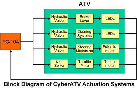
The throttle function is actuated by an R/C servomotor, whereas the automatic steering, braking and
gearing functions are actuated hydraulically. Turning the steering requires considerable torque when the
vehicle is stationary or moving at low speed, and the amount of space for mounting actuators on the
steering is fairly limited. A hydraulic actuator was therefore chosen due to its high power-to-weight ratio
and resulting compact size relative to a comparably powerful electric motor. The same hydraulic system
was then used for gearing and braking. A block diagram of Lewis actuation is shown in Figure 3.
1.1 Steering Actuator
The steering actuation consists of a 4.5" hydraulic piston aligned parallel to the steering push rod on the
right front wheel (from the rider's view). The rod end of the cylinder is attached to the suspension crank
arm. The cap end of the cylinder has a trunnion mount and is attached to the ATV chassis. A proportional
directional control valve is used to control hydraulic flow to the steering cylinder. The flow output of the
valve can be affected by a variable voltage input command between 0 and 10 volts [7]. The slew rate,
rather than the position, of the steering is roughly proportional to this command. A resistive linear
potentiometer is incorporated at the cap end of the cylinder to provide feedback (0-5 volts) and is connected
to a DM5416 Real-Time Devices analog/digital I/O board on the PC/104 stack.
1.2 Gear Actuator
Two linear hydraulic actuators are mounted back-to-back for shifting into neutral, high and reverse gears.
The two cylinders are connected to the gear selection assembly by an adjustable rod. Neutral position
corresponds to cylinder 1 retracted and cylinder 2 extended, high gear corresponds to cylinder 1 retracted
and cylinder 2 retracted, and reverse gear corresponds to cylinder 1 extended and cylinder 2 extended. A
three-way control valve is used to control the hydraulic linear actuators [7]. The existing ATV gear
selection light is used for feedback and is connected to a DM 5416 Real-Time Devices analog/digital I/O
board on the PC/104 stack.
1.3 Brake Actuator
The pre-retrofit ATV braking system consists of a single-lever, all-wheel hydraulic disc brakes and a
hydraulic rear foot brake. In the retrofit, only the rear brake is actuated, using a low-profile air/oil cylinder.
A directional control valve is used to control the brake cylinder. This nominally provides for only on/off
braking, but the brake can be pumped, or cycled, at different rates in order to provide intermediate levels of
braking. There is no explicit feedback from the brake.
1.4 Hydraulic System
The hydraulic pump is a Parker series D gear pump equipped with an integral four-quart reservoir and a
system relief valve. The pump is driven by a NEMA 56 C frame single-phase AC motor which uses a
120 V AC input. The pump motor is controlled by a single solid-state AC contactor located inside the
electric enclosure [7]. To reduce heat and power, the pump circuit includes an unloading valve circuit to
dump fluid at low pressure when high-pressure fluid is not required. A 2-quart piston-type accumulator is
included in the circuit to reduce pressure instabilities.
1.5 Throttle Actuator
The ATV is equipped with a 4-stroke, liquid-cooled engine with a 34-mm Mikus carburetor, which is
regulated by a throttle plate. A Futaba R/C servomotor is used to accomplish the opening and closing of the
throttle plate via two cables. One cable connects the servo to the throttle control lever on the handlebar,
while a second cable connects the servo to the throttle plate. Each cable is passed through a friction clamp that holds
the cable in place and also provides a means to adjust the length of the cable. The throttle plate setup incorporates a
torsional spring, which applies a closing torque on the throttle plate sufficient to back-drive
the servo to idle throttle position when power is turned off. The choice of an R/C servo for throttle
actuation is based on its low cost, small size, internal closed-loop position control, low power consumption
and easy control signal generation. Speed feedback is obtained via a tach generator mounted in the gearbox.
The tachometer is a Servo-Tek SB-763-2 A, designed for use in applications requiring an output signal
between 1 and 10 volts/1000 RPM. The output of the tachometer is connected to a DM5416 Real-Time
Devices analog/digital I/O board on the PC/104 stack.
2.0 Computer System
The computational architecture is two-tiered: locomotion (low-level processing) is performed by a PC/104,
while planning, perception, and communications (high-level processing) are performed by a set of three
networked PCs in a custom housing mounted on the front of the vehicle.
The PC/104's economy of size (4 by 4-inch cards), low power requirements, and mechanically rugged
design are well suited for outdoor applications. Further advantages are the availability of components from
a variety of vendors and the ability to use virtually all of the program development tools used for IBM PCs.
The configuration of the PC/104 employed includes four boards from three different vendors:
· One Versalogic VSBC-2 CPU featuring a 32-bit, 133 MHz, 5x86 CPU chip. Its performance is
equivalent to a Pentium 75 MHz machine.
· One WinSystems PCM-COM4A serial interface board. This board is a 4-channel serial INS
8250-compatible PC/104 module. Each channel supports RS-232, with RS-485 and RS-422
as options.
· One WinSystems PC/104 video board, the PCM-FPVGA. It supports standard VGA CRT output as
well as a variety of flat panel displays using optional flat-panel adapter (FPA) modules. Other options
include multi-video display capability, PC video input, and NTSC video output.
· One DM5416 analog/digital I/O board from Real-Time Devices. The DM5416 has 8 differential or 16
single-ended analog input channels with an input range of -10 to +10 volts, 8 bit-programmable digital
I/O lines with advanced digital interrupt modes, one 16-bit digital-to-analog output channel, 8 port-programmable
digital I/O lines, two 16-bit timer/counters, and an 8 MHz clock.
The high-level processing suite consists of 3 Pentium II 350MHz PCs, each equipped with Ethernet card,
Matrox frame grabbers. Each PC has access to all the cameras on the ATV via a customized designed
terminal switch. Each PC controls one pan/tilt mechanism. The three PCs are connected together in a star
network with cable segments to a hub. The wiring employed on the star-based network is 10Base-T, but
different cable types can be used to connect to the hub if higher bandwidth is desired.
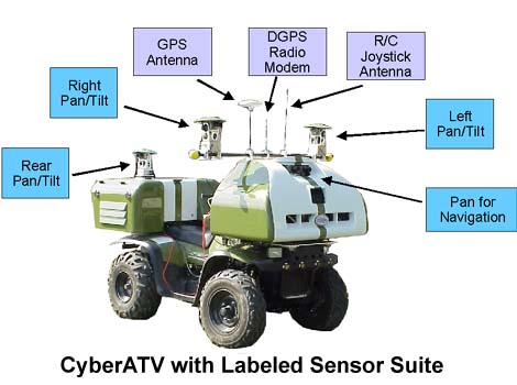
3.0 Sensors
Figure 4 depicts Lewis with sensors labeled. Navigational sensing is performed by a 20-cm resolution
NovAtel DGPS unit. Perceptual sensing is currently restricted to vision, which we are trying to exploit to
the fullest due to its passive, unobtrusive nature. Currently each vehicle is equipped with five cameras, a
panning stereo pair in front for obstacle avoidance and mapping, and three pan/tilt cameras for surveillance,
one each located at the front left, front right, and rear. Stereo vision is employed to have a 3-dimensional
understanding of the environment to perform free space mapping, thus enabling obstacle detection and
path-planning. Further details about CyberATV's perceptual sensing can be found in [1].
4.0 Communications
Communications between the low-level and high-level processors are currently via a serial cable, but can
be upgraded to wired Ethernet if increased bandwidth is desired. Communications with other platforms and
with remote users are performed via wireless Ethernet using 915MHz Wavelan technology.
5.0 Power System
Consideration was given to adding a take-off to the vehicle clutch in order to provide power for the systems
added to the vehicle by the retrofit. We discarded this solution, however, for two reasons. First, it was
mechanically infeasible due to excessive motion of the clutch drive shaft. Second, the amount of power
available from the alternator was projected to be insufficient. As a result, a 2.5kW Honda generator was
mounted on the rear of the vehicle to provide auxiliary power.
The generator provides two 120V AC, 15A outputs. One of these powers the hydraulic motor. The other is
converted to 24V, 12V and 5V DC for use by the sensors, relays, optoisolators, and hydraulic valves. 5
volts are supplied separately to the PC/104 by the ATV's battery via a 12-to-5V DC converter.
 |
