Scribe Notes -- January 26, 1998
 Slide 1: FPGA Arithmetic II
Arithmetic is important in realms where DSPs are traditionally applied.
 Slide 2: The Wallace Tree
Once the partial products are computed, adding them takes time.
A tree of partial products is built to add them together. Full adders
in this tree take 3 bits from each column and generate a sum and carry
bit. The carry bit goes into the more significant position in the
result, and the sum goes into the less significant bit.
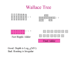 Slide 3: Wallace Tree
This reduction of bits is repeated until the multiplication is complete.
If there are 2 bits in a column, a half adder is used instead of a full
adder. The advantage of a Wallace tree over other adders is that
the critical path is no longer linear with the number of bits, it is log3/2
instead: this is because each stage reduces 3 bits to 2 bits. The critical
path is down the diagonal and accross the bottom adder. This circuit can
not use the fast carry logic effectively because many blocks have 2 carry
ins. The routing of this is irregular, making it difficult to fit in an
FPGA nicely. Multiply and add can be implemented with little incremental
cost over just a multiply, because the add can be integrated into the Wallace
tree.
 Slide 4: Partial Product Generation
Using AND gates for partial product generation wastes LUT resources. The AND gate may not be subsumed into the LUT. Use small multipliers.
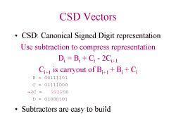 Slide 5: CSD Vectors
Binary encoding has each bit represent a number of the form {0,1}2n.
CSD encoding uses {-1,0,1}2n. To encode this: C = (B + (B<<1)).
-2C is C shifted 1 to the right and multiplied by 2. So the final
result, D, contains -1's, 0's and 1's. For an n bit number, there can only
be n/2 non-zero digits in a CSD expression.
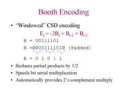 Slide 6: Booth Encoding
The digits of the encoded number, E, are one of {1,0,-1,-2}.
Each bit position in E corresponds to (..., 26, 24,
22, 20), unlike binary where they are (..., 28,
24, 22, 20). Each digit in E is
computed by selecting a group of 3 digits in the original number, adding
the two least significant bits, and then subtracting 2 times the most significant
bit. In this example, E = 26-22+20.
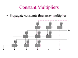 Slide 7: Constant Multipliers
Can eliminate adders with 0's on the inputs. This can drastically reduce
the number of adders. In addition, the and gates can be eliminated.
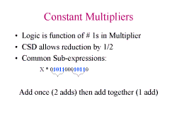 Slide 8: Constant Multipliers
CSD reduces the complexity of a multiplier by encoding a multiply as
an add followed by a subtract. i.e. 101111 = 110000 - 000001. Common
sub-expressions reduce the amount of circuitry required at the expense
of having more wires.
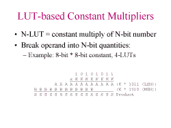 Slide 9: LUT-Based Constant Multipliers
A 4 bit constant with a 4 bit operand produces an 8 bit product. An
array of LUTs can be used to implement a 4->8 multiplier.
 Slide 10: LUT-Based Constant Multipliers
This diagram shows the layout of a circuit that does the computation
shown on the previous slide. 8 bits come in top of this diagram into
12 different 4-LUTs. Each set of 4-LUTs produces 3 four bit vectors
-- the three vectors on the left are added to the top two vectors on the
right, and concatenated with the lower vector on the right. This
can be arranged in a tree structure for larger multipliers. An interesting
point is that the constants can be changed in the LUT SRAM without changing
the wiring to produce new constant multipliers. This allows a single
constant multiplier to be dynamically loaded with new constants.
 Slide 11: Distributed Arithmetic
Can be extended by taking more bits from the input at once, but this
begins to look like a LUT based multiplier.
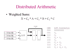 Slide 12: Distributed Arithmetic
This combination allows a convolution to be computed at the same time
as performing the multiplication.
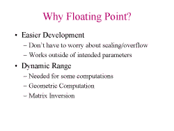 Slide 13: Why Floating Point?
Another reason is that FP may improve resiliance to quantization error.
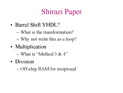 Slide 14: Shirazi Paper
There are multiple errors in the paper, including:
-
(e2-e1) should be (e1-e2) in section 3.1, under "Stage 2" of the adder
algorithm.
-
The columns are not aligned correctly in the multiplication diagram in
the upper left corner of page 160
-
A shift is missing somewhere else (??? - I missed where this was...)
The algorithms presented do not account for the values 0, plus or minus
infinity, or NaN.
Barrel Shift VHDL:
The barrel shifter should not have to be expanded into a unrolled loop.
The initial implementation uses a linear chain of MUXs to perform the shifting,
while the unrolled version uses a logarithmic number of layers. The log
version should be expressible as a loop as well.
What is "Method 3 & 4?":
-
Faster versions of the multiplier, at the cost of a deeper pipeline
-
Version 4 using Ferrari-Steffanelli Division
Using off chip RAM for looking up reciprocals is only practical in SPLASH. Not a general purpose solution.
Why not pipeline the addition?
This makes convolution harder, since multiple sums would be in the pipeline
at once, and these sums would then have to be added themselves to complete
the convolution.
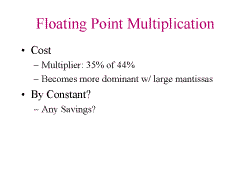 Slide 15: Floating Point Multiplication
The size of the integer multiplier dominates the circuit, especially
as n increases. The adder is the same size as the multiplier.
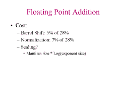 Slide 16: Floating Point Addition
 Slide 17: Floating Point on FPGAs
What features would improve FP performance if they were on an FPGA?
-
Fast barrel shifters
-
2-1 mux is implemented as a 4-LUT, which means upwards of 1600 transistors
of configuration logic is being used for what could be a 6 transistor gate.
-
Programmable MUXs could alleviate this
How expandable are these algorithms?
How about 32 bit FP?
Distribute accross FPGAs? Does this work?
How many bits are required to solve the problem at hand?
-
The smaller the number of bits, the faster the circuit can go.
Can a 12 bit FP FPGA beat a 64 bit Alpha?
Numbers such as NaN and infinity were ignored by this paper. How important
are they? How much logic would be needed to handle them?
Crazy idea: Dynamic reconfiguration can be used instead of floating
point. If an adder determines that the next stage of a calculation will
overflow or underflow, have it reconfigure the next stage to use a different
number of bits for computation, or for it to move its fixed decimal point
left or right. Alternatively, if a calculation is using fixed coefficients,
the compiler could figure out what precision to use at each stage of a
calculation. The FIR filter was made using general purpose multipliers.
Why not use specialized multipliers at each stage?
Scribed by Chris Colohan