SolidWorks Intro Part 2
Dave Touretzky
Starting SolidWorks on the Laptops
- Log in with your Andrew id.
- Search for and run program: "Solidworks 2018 x64".
- Turn off any unneeded add-ins.
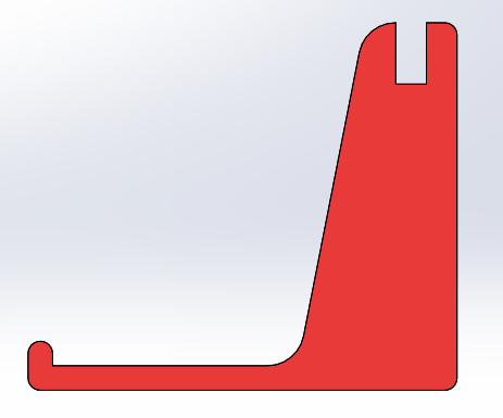
MAKING A PHONE OR BUSINESS CARD STAND:
- Start a new part.
- Turn off "Instant 3D" in the Features tab if it's on.
- Create an Extruded Base on the front plane.
- From the origin, draw a horizonal line of length roughly 3.5 inches. Lengths
need not be exact at this stage.
- From the right edge of that horizontal line, draw a vertical line extending upward by roughly 3 inches.
- From the top of that vertical line, draw a horizontal line to the left,
with a length of about 0.75 inches.
- From the origin, draw a vertical line of length 0.4 inches.
- Then continue with four more lines, making sure that each snaps to the endpoint of the preceding line:
- Come right 0.2 inches.
- Come down 0.2 inches.
- Come right 2 inches.
- Come diagonally up and to the right to close the figure.
Dimensioning:
- Select the Smart Dimension tool.
- Dimension the right vertical line to 3 inches.
- Dimension the bottom horizontal line 3.5 inches.
- Dimension the top horizontal line to 0.75 inches.
- Dimension the left vertical line to 0.4 inches.
- Dimension the short horizontal and vertical lines to 0.2 inches.
- Dimension the remaining horizontal line to 2 inches.
- The sketch should now be fully defined: all lines have turned black.
- Click Exit Sketch and set the extrude depth to 1/8 inch.
- Color your part red.
- Save it as StandPiece.SLDPRT.
Filleting:
- Create a Fillet feature and put 0.1 inch fillets on all the convex edges of the part,
except for the top left edge.
- Create another Fillet feature and put 0.3 inch fillets on the top left edge and the
big concave corner.
- Save the part.
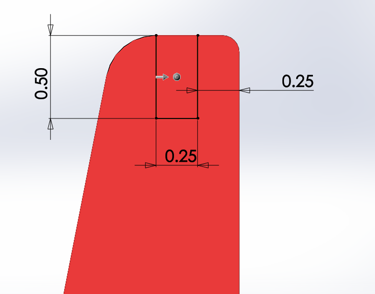
Cutting the Slots:
- Create an Extruded Cut feature on the face of the part.
- To cut the top slot, draw three lines forming a U shape. The tops of the two vertical
lines should snap to the top edge of the part.
- Dimension the horizontal line forming the bottom of the slot to 0.25 inches.
- Dimension one of the vertical lines of the slot to 0.5 inches.
- Add an Equal relation between the two vertical lines.
- Dimension the distance between the right vertical line and the right edge of the part to 0.25 inches.
- Click Exit Sketch.
- In the Extruded Cut dialog, look in the graphics window and you will see a gray arrow showing
the direction to cut. If the arrow is pointing outside the slot, click on the
"Flip side to cut" checkbox in the dialog pane.
- Click OK to complete the extruded cut.
- In the left pane, switch from the Feature Manager tab to the Configuration Manager tab.
- Click on "Default" and rename the configuration to "StandA".
- Save the part.
- Right click on the part name (StandPiece) and select "Add Configuration".
- Name the new configuration "StandB".
- Go back to the Feature Manager tab.
- Click on the Extruded Cut feature and select Suppress from the shortcut menu to suppress the feature.
- Click on the "+" to open the Cut Extrude feature, revealing its sketch.
- Click on the Extruded Cut sketch and select "show" from the shortcut menu to make the sketch visible.
- Create a new Extruded Cut feature on the face of the part.
- Draw three lines forming the complementary slot. The bottom edges of the vertical lines should
be snapped to the bottom edges of the part. The horizontal line should match the horizontal line
of the earlier sketch. If snapped properly, all three lines will be fully defined; no
dimensioning is required.
- Click Exit Sketch.
- In the Extruded Cut dialog, check the direction of the gray arrow and click on the
"Flip side to cut" checkbox if the arrow doesn't point to the inside of the slot.
- Click OK to complete the Extruded Cut.
- In the Feature Manager tree, click on the exposed sketch of the first Extruded Cut and
select "Hide" form the shortcut menu.
- In the left pane, switch from the Feature Manager to the Configuration Manager.
- Double click on "StandA" to make that the current configuration.
- Notice that the second Extruded Cut feature is suppressed and the first is not.
- Save the part.

- Add a third Extruded Cut feature and make some decorative cutouts
using hexagons, circles, ellipses, or closed curves, but make sure they don't
overlap with either of the slots. (You can make both slots sketches visible
to help you check this.) At least one of these decorative cutouts should be a circle;
we'll use this later.

- Make sure the third Extruded Cut feature is unsuppressed in both configurations.
- Switch back to the StandA configuration and save the part in that configuration.
Assemblies
- Click on the New icon or hit control-N to make a new file.
- Select "Assembly" rather than "Part".
- Click on StandPiece from the "Begin Assembly" menu and drag it onto the workspace.
- Notice that StandPiece appears in the Feature Manager tree.
- The "(f)" to the left of the name indicates that the part's position is "fixed". The first
part of an assembly is fixed by default; the remaining parts float until mated.
- You can toggle between Fixed and Float by right clicking on a part.
- Click on "Insert Components" and insert another StandPiece part next to the first one.
- Verify that you can drag the second part around, but not the first one (because it's fixed).
First Set of Mates:
- Click on the Mate tool.
- Click on the largest face of a StandPiece instance.
- Click on the matching face of the second part.
- Click OK to accept the mate.
- Now you can click and drag on the floating part and verify that it's still movable,
but it is constrained to the plane of the mated face.
- Add two more face mates, using mutually orthogonal faces (e.g., the back and bottom faces),
to fully mate the parts.
- Remember that you must accept a mate (click the green OK check mark) before you can make another.
- Click and drag on a part and notice that its motion is now constrained.
How to delete a mate:
- Quit the mate tool.
- Click on a part and select the View Mates icon. Or...
- Go to the Feature Manager Tree and open the Mates attribute to see all mates.
- Mouse over a mate to visualize it; hit Delete (function-Delete on Macs) to remove it.
Second Component:
- Insert another Standpiece part into the assembly.
- Switch the part to the StandB configuration: click on the part and select "Component Properties"
from the shortcut menu.
- In the Component Properties dialog box, click on StandB, then click OK.
- Color the part blue:
- Click on the part
- Click on the Appearance pulldown (the beach ball) in the shortcut menu, then click on "Body"
rather than "StandPiece".
- Click on the "Apply at component level" radio button, because we only want to change
the color of this one instance of StandPiece.
- Click on blue from the color picker.
- Clock OK.
- Control-left-click on the StandB part and drag the mouse; this creates a copy of the part.
- Color that part blue as well.
Second Set of Mates:
- Mate the two blue StandB pieces together, but instead of mating faces, we'll mate edges.
- Start by mating the large vertical edges at the back of the part.
- Next mate two bottom edges.
- You'll note that two orthogonal edge mates are sufficient to fully mate the parts.
- Exit the mate tool.
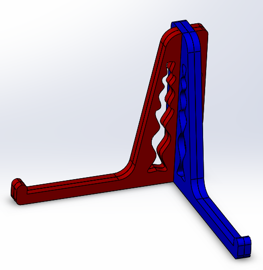
- Now we want to mate StandB to StandA.
- Right click on StandB and select "Move with Triad".
- Move the mouse onto the rings until a ring turns orange; then click and drag.
- Rotate StandB so that it's roughly perpendicular to StandA.
- In the mate tool, select a long vertical face in the interior of StandB's slot.
- Select the broad face of StandB.
- Repeat the process two more times, mating complementary faces, until the parts are fully mated.
- Save your assembly as Stand.SLDASM.
How to make plastic parts:
- SLDPRT files -SolidWorks->
- SLDDRW file -SolidWorks->
- DXF file -Inkscape->
- colored DXF file -LaserDriver-> plastic
Drawings

- Click on the New icon or press control-N.
- Select "Drawing" rather than "Part" or "Assembly".
- Uncheck the "Display sheet format" box if it's checked.
- Select "Custom sheet size" and set it to 12 x 12 inches.
- Right click on "Sheet1" and select Properties; make sure the scale is 1:1.
- From the View Layout tab, select Model View.
- Click on StandPiece, then click the blue right arrow.
- Click in the graphics area to place the part.
- Move the mouse and you'll see it wants to insert another view.
- Hit Escape to stop inserting views.
- Click on the drawing and verify in the Drawing View dialog box that the configuration is StandA
and the scale is "Use sheet scale".
- Click on the centerlines in the circles and delete them (function-Delete on the Mac).
- Add a second StandPiece to the drawing, and set its configuration to StandB.
- Laying out parts to cut:
- Try to save plastic: rotate and nest StandB within StandA to avoid waste.
- Right click on StandB and click on Zoom/Pan/Rotate, then select Rotate View.
- Left click, and drag the mouse to rotate the part.
- Release the mouse when the part is at the desired angle, and hit Escape to finish the rotation.
- Save the drawing as Stand.SLDDRW
- Then save it again as a DXF file.
Using Inkscape to Color Your DXF File

- Run Inkscape from the Start button. Note: it's slow to start.
- Go to File -> Open, then set the file type in the dialog box to "AutoCAD DXF R13".
- Open your DXF file.
- Turn off A4 scaling and set the manual scale factor to 25.4.
- Zoom out and select the "Solidworks Educational Edition" banner, hit Delete to remove it.
- Note: on MacBooks you must press function-Delete.
- Hit control-A to select everything.
- Set the color to blue by holding down the SHIFT key and clicking on the blue color patch.
- Note: use red lines for internal features, blue lines for external boundaries.
- Select the internal countours and color them to red.
- If you click instead of SHIFT-click on a color, you will fill the region.
Type control-Z to undo.
- Do File -> Save As and set the file type to "Desktop Cutting Plotter (AutoCAD DXF R14)". Then...
- Click "Save", set the base units to "mm", and click OK.
|