
In the first part of this project, I created panoramas in which the actual stitching process is automatic but the determination of correspondences still requires human input. In the second part of this project, I added the ability to automatically find correspondences between points. The work in Part II is heavily based on the paper Multi-Image Matching using Multi-Scale Oriented Patches , which describes Harris corners, ANMS, and the MOPS descriptor. The course notes describe the RANSAC algorithm and the stitching method, which is carried over from Part I.
Since panorama stitching works best when photographing landscapes or planar surfaces, I went to the University of Pittsburgh's Cathedral of Learning, initially planning to photograph the city of Pittsburgh from the top. I changed my mind, however, when I found that the nationality rooms were open. Enjoy the photos!
To stitch panoramas in Part I, I hand-selected correspondence points in two images, and morphed the first to match the second. Then I blended them together using a two-level pyramid, with linear blending for the low-frequency data and a binary mask for the high-frequency data.
In Part II, the procedure is the same, except that the correspondence point selection is automatic. I first use the course-supplied Harris corners function, then choose 500 corners from each image with Adaptive Non-Maximal Suppression (ANMS), which will be described later. All the points drawn in red or green below are the corners left after ANMS. I take a 40 x 40 window around each corner, and average 5 x 5 blocks from that window to create a 64-dimensional descriptor (the MOPS descriptor) for each point. The next step is to match the descriptors to each other. I match these descriptors based on the distance between pairs of the 64-dimensional vectors, and keep each match in which the distance from the point in the first image to the closest match in the second image is less than one-half the distance from the point in the first image to the second-closest match. From there, I use RANSAC to refine the matches so that only good matches are left, and from this point the process is exactly the same as in Part II. I use the good matches to compute a homography for warping the first image to match the second, warp the first image using this homography matrix, and blend the warped image with the second image.
In each of these blending tasks, I show six images. The first two are the original images. The next two are the images with 500 Harris corners drawn. Each corner that has some match in the other image is drawn in green, and each of the other corners left after ANMS is drawn in red. The final two images are the stitched images. The first stitched image is the one in which I hand-selected correspondence points during Part I of this project, and the second stitched image is the one in which my code automatically selected correspondence points from the green set during Part II. As you can see, the output with algorithmically chosen points is very similar to the output with hand-chosen points. The exception in these three panoramas I made is the first image, of tiles from the wall of the Ukraine room. The image based on automatically chosen correspondence points looks less blurry in the overlap region than does the image based on manually chosen correspondences.


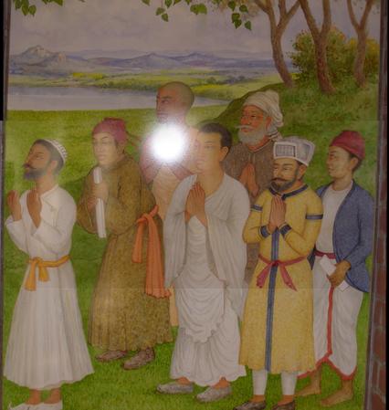
This came out amazingly well. As a comparison, I took a picture of the entire painting. Look at how closely the panorama and the real thing match.


This one came out more blurry than the tiles from the Ukraine room. I think this panorama came out blurred not because of small errors in the correspondence point selection, although that was certainly a factor, but because there are large flat areas on the wooden wall that are hard for human or computer to match between the two images.
Here I morph images without blending them. The target for the warp was to move the imaging plane so that the wall or floor would appear to be facing directly at the camera. I'll show the input image first, and the morphed image second.


ANMS works by taking a huge number of corners from a Harris corners function (the function on the course website generates about 97000 for each of the 2112 x 2816 images I feed to it), and then ranks them not solely by their strength as corners, but also by their distance from other corners. Each corner i is assigned a score ri, based on the comparative strength of the corners around it, and ANMS keeps the 500 corners with the highest ri scores, rather than raw scores.
As an example, consider an image taken from the Turkey Room in the Cathedral of Learning:

If we simply take the highest-scoring 500 Harris corners, all the corners end up bunched around the textured features in the image.

On the other hand, using ANMS generates corners that are much more nicely spread out, which will make matching easier during later stages of the panorama making process.
