
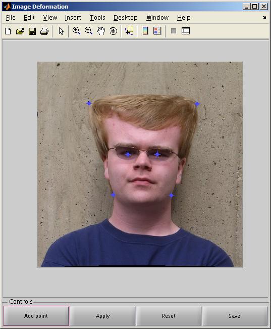
I have implemented the method of image deformation described in this paper from SIGGRAPH 2006 by Schaefer et al. I made the functionality accessible through a function that takes an image and control point pairs that define the morph. Given that, I integrated the method into our face-morphing code from the third project but found no significant differences in the results. That having failed, I retargeted my efforts toward providing an interactive interface for the deformation.
After beginning this project (I swear!) it was pointed out to me that the method of image deformation described in the above-referenced paper was assigned as a class project by Professor David Martin of Boston College. His notes for the assignment proved a valuable aid to interpreting the paper.


I used the moving least squares method of deformation and recreated some of my results from project 3. However, as can be seen from the examples below, the differences between the simple triangle-mesh method and the more complicated moving least squares method were not exactly groundbreaking. This was most likely because of the large number of correspondence points (40+) used, which very tightly defined the transformation.

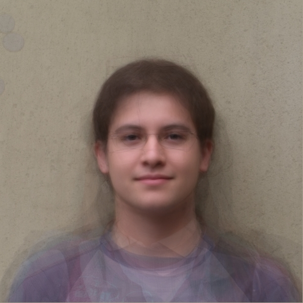
The "average" face colors warped onto the "average" face mesh.
On the left is the project 3 version
On the right is the MLS version
Largely the same, though the MLS version is a little blurrier.

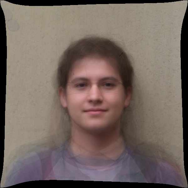
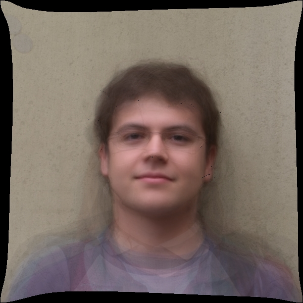
The "average" face colors warped onto my face mesh.
On the left is the project 3 version
On the right is the MLS version
The MLS version avoids some of the distortion at the nose by smoothing the transformation.

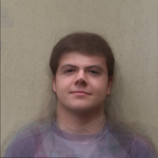
My face colors warped onto the "average" face mesh.
On the left is the project 3 version
On the right is the MLS version
It seems I have a really weirdly shaped (or labeled) nose. Again, though, the MLS transformation is a little more forgiving.

Halfway between myself and Ronit.
As always, P3 result on the left, MLS on the right.
Also available: a 1200x600 comparison movie of the entire morph (61 frames).
Unsatisfied with the results I got from merely redoing project 3, I found an example of an instance where project 3 really failed, and MLS really excelled. The key: use very few correspondence points. MLS interpolates with pleasing results; the project 3 method... doesn't.

With apologies to Matt Banner.
Only four correspondence points were used to create these images. The project 3 version on the left obviously didn't produce a smooth transformation, while the MLS version on the right produced a "realistic" transformation--at least, as realistic a transformation as one might hope for in turning their friend into an alien from Mars Attacks!

Since my project closely mirrors an assignment that I imagine at least one professor would like to reuse, I will refrain from posting my code here. If you are interested in seeing it, please contact me.