
This is an extension to project 5, which is the tour into picture from a single view. In project 5, we create the system using only 1 vanishing point, and only from 1 single input image. Although it is good enough, real scene in the world is rarely composed of only 1 vanishing point. A system which exhibits 2 vanishing point perspective model will give us more appealing tour. This this system will generate the 3D model based on the 2 vanishing point perspective. For this, user will have to specify the base lines in the given images. User will also need to specify parallel lines for vanishing points calculation, or they can simply input the horizon location.

Then, the estimated horizon line is computed as shown below:
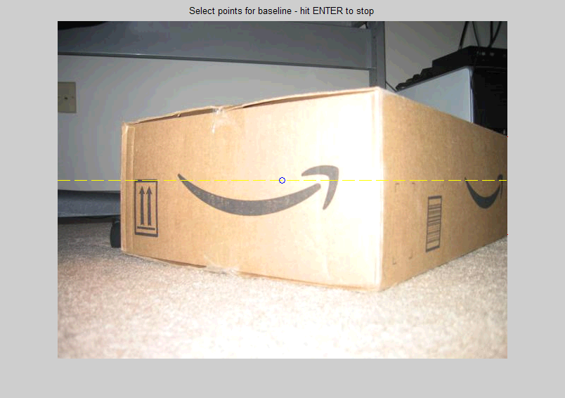
Base Lines Collection
User will specify sets of base lines to build vertical walls. The following image shows the process. Yellow lines denotes the horizon line. Blue circle denotes the camera vanishing point.

Height Collection
User will specify the desired height for his 3D model. The following image shows the process:

Ground Surface
Ground surface is assumed to be a perfect rectangle plane lying on z=0. The texture is warped properly to this new shape, taking into account the distance of each pixel from the real camera coordinate. We extract the ground texture as shown below:

Wall Surface
Similarly, we compute the wall surfaces based on the baselines and the heights.
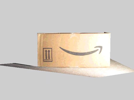
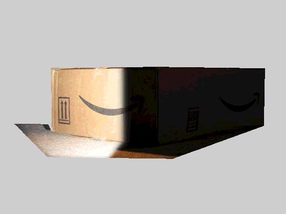
Finally, we create the 3D surfaces and wrap the warped textures to these surface. Here's what we get:


Sources


Building View
Source

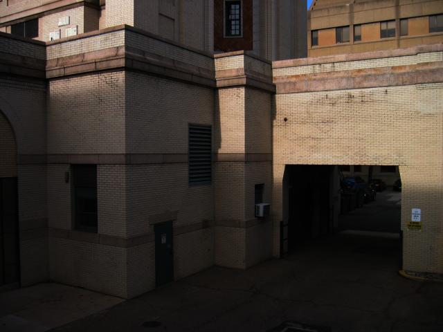
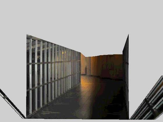
Results


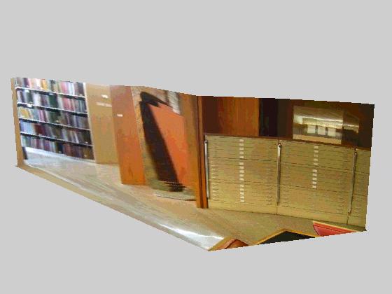
Library
Source

Results

Newell Simon Bridge
Source


Results


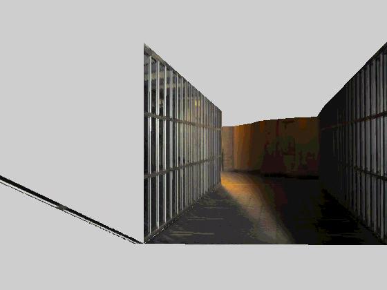
Note: the distortion on the sides is because it's assumed to be a ground plane. This depends on how user selects the wall.
Park View
Source

Results


All input images can be found here and all results can be found here. Sample intermediate results can be found here.